Overview
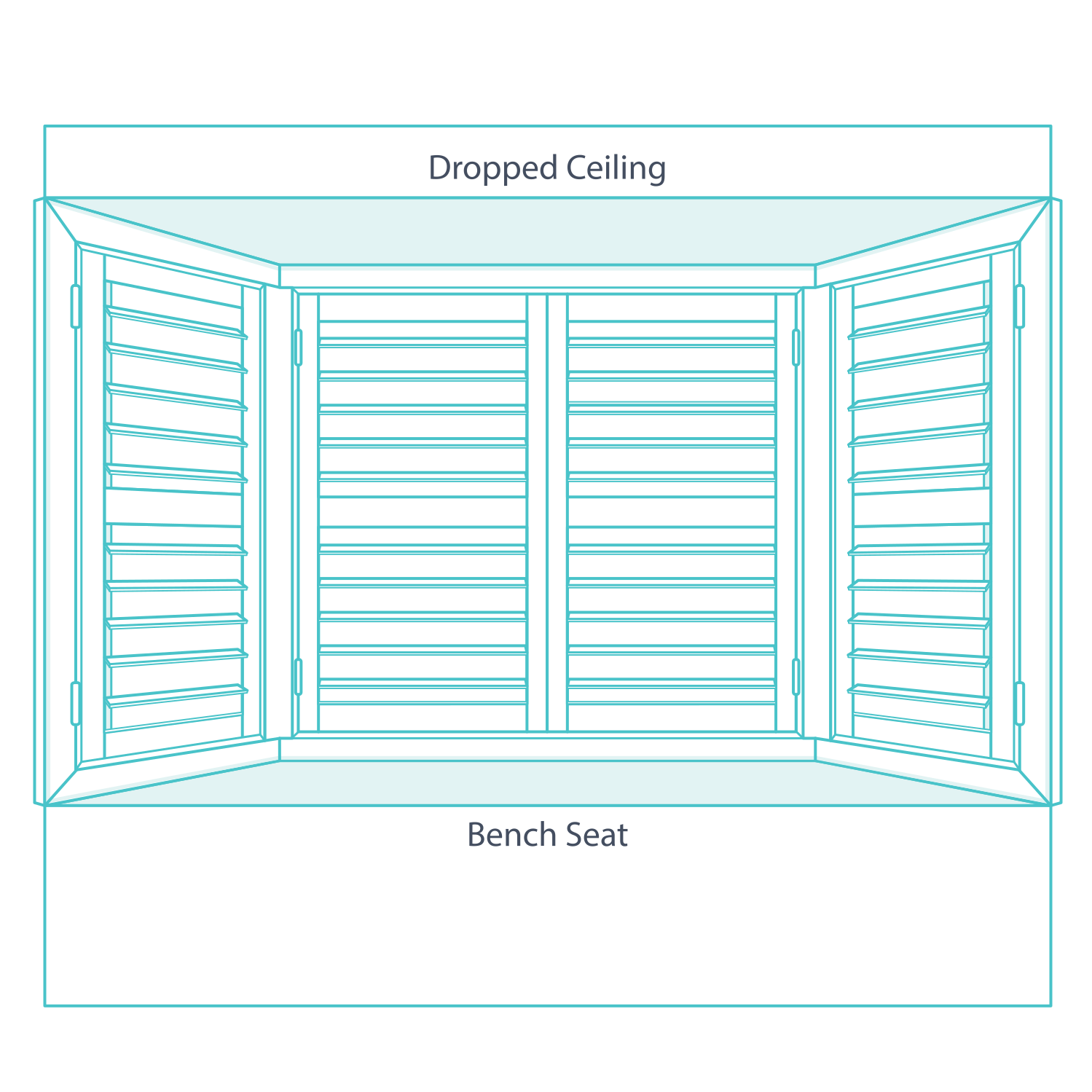
A bay has three connected faces and two junctions. Plan the left, centre and right shutters together with the bay posts. Confirm both angles, select the mount and establish each junction's reference before recording the individual widths.
What Is a Bay Window?
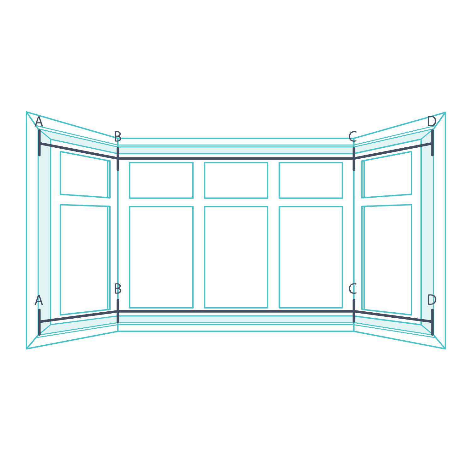
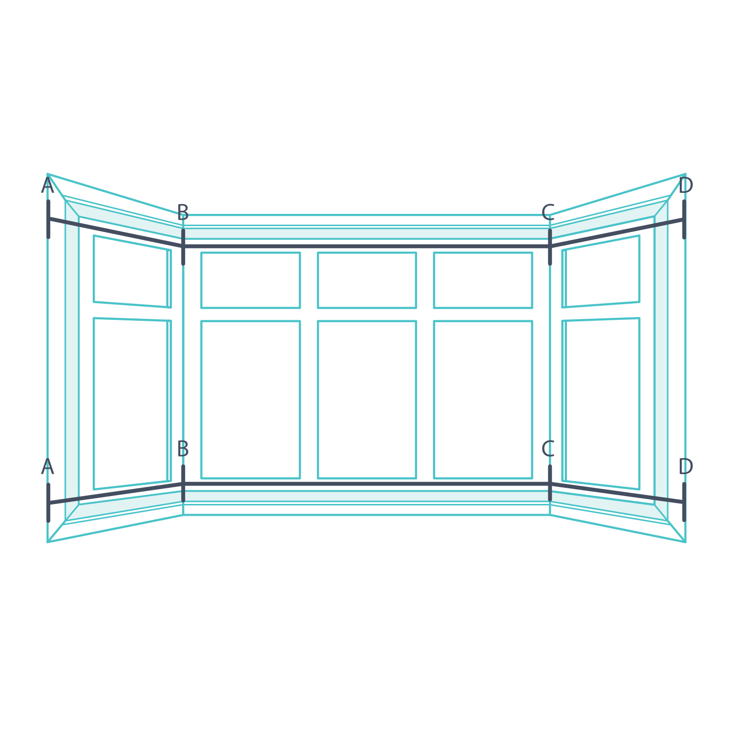
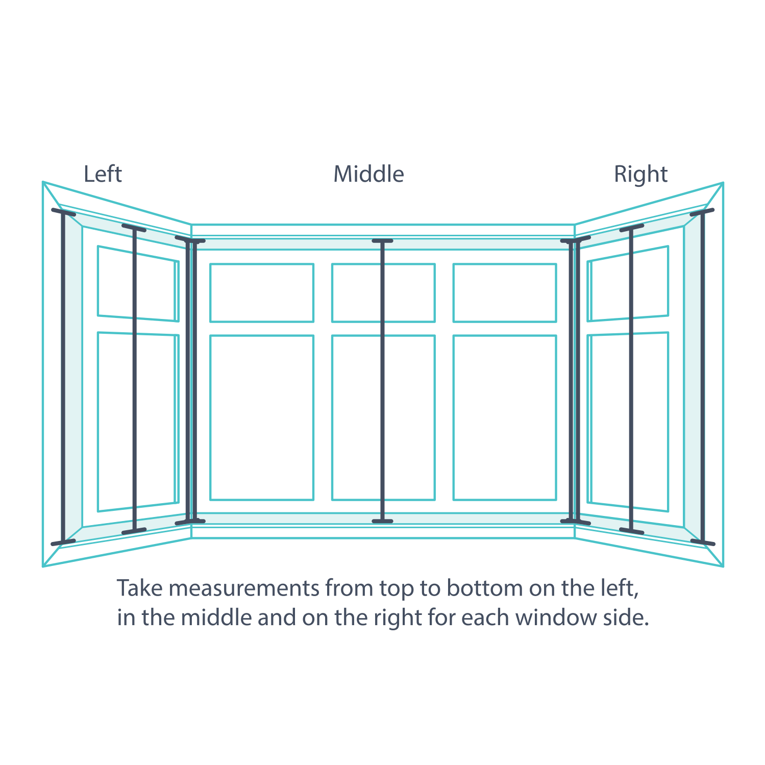
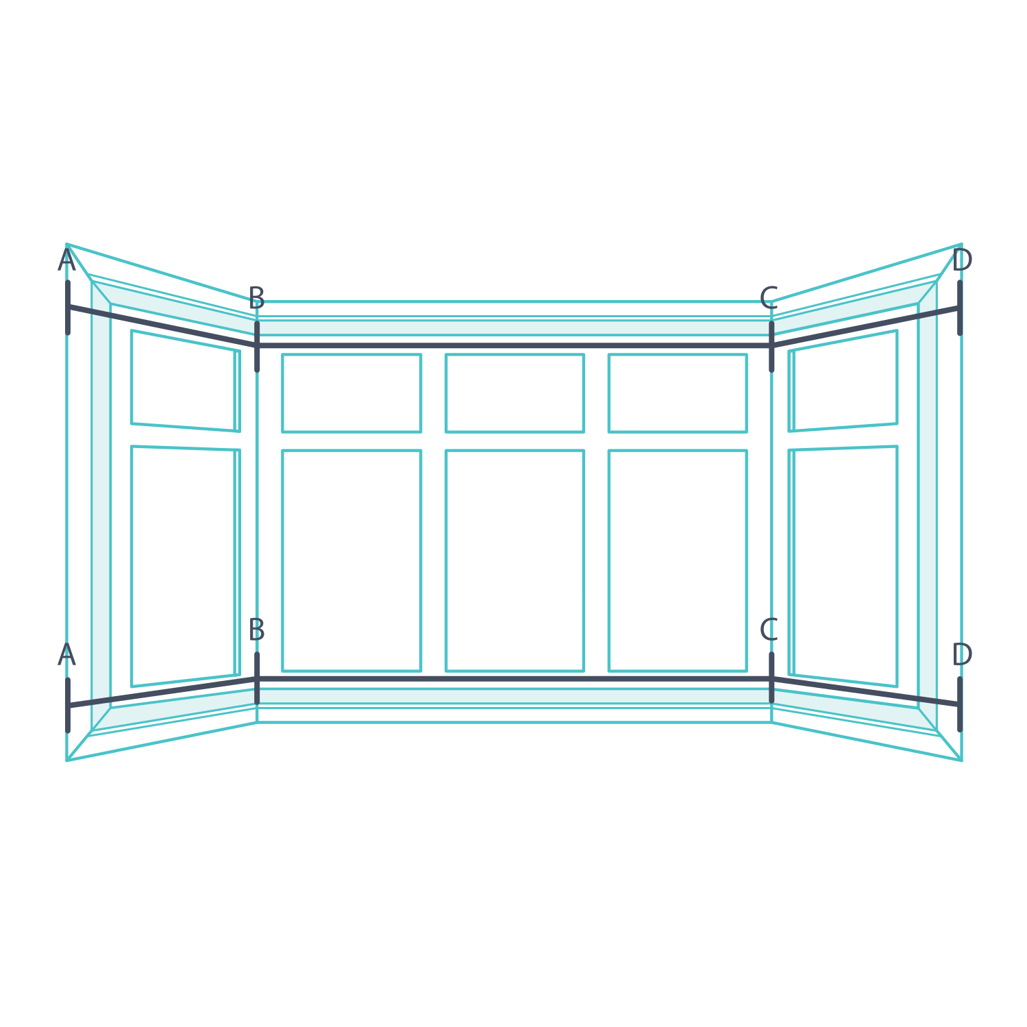
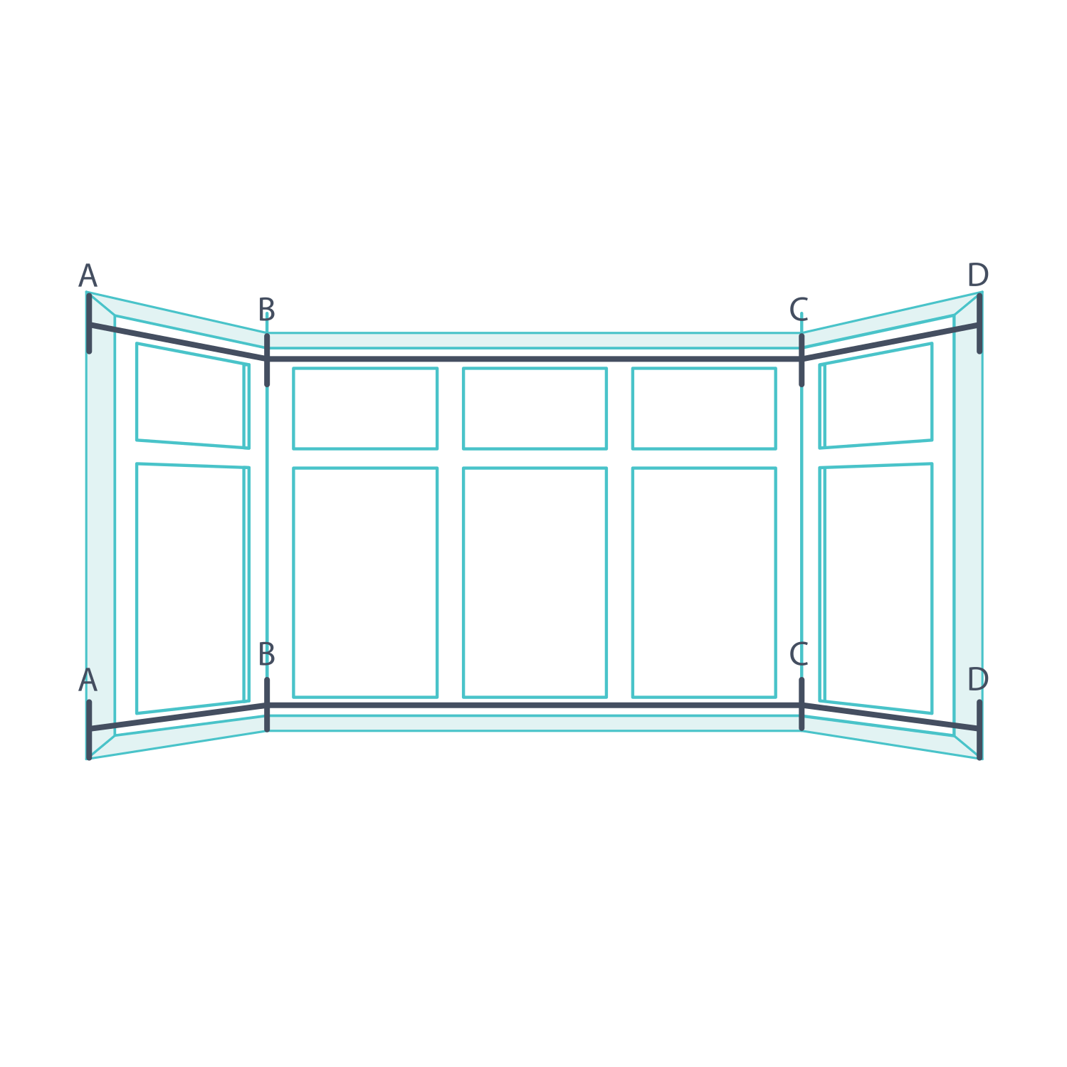
A typical bay has three faces: left A–B, centre B–C and right C–D. The side faces meet the centre at approximately 45° in plan. Treat all three as one arrangement so the bay posts, frames and panel lines meet correctly.
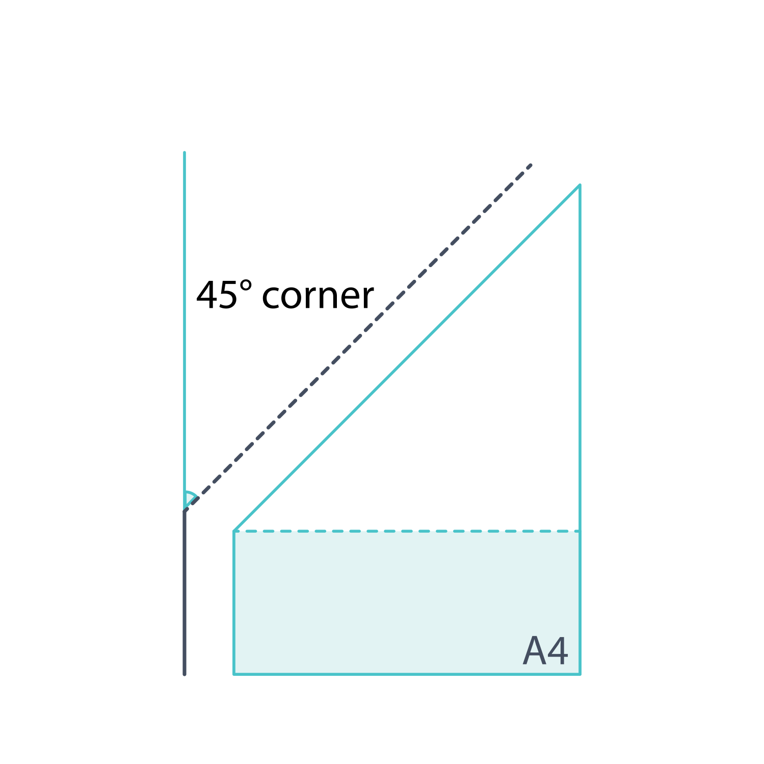
Determine if your corner window is 45 degrees
Fold an A4 sheet to form a 45° guide and compare it with each bay junction as illustrated. Check both sides rather than assuming they match. Send a measured plan and photographs if either angle differs from the standard arrangement.
Plan all three bay faces
Choose the mount before measuring. Label the faces Bay Left, Bay Centre and Bay Right under one room name. Use a steel tape and pencil, and draw both junctions in plan view. My Direct asks for bay shutter dimensions and photographs to be checked with the team before ordering.
Measuring for an Inside L-Frame
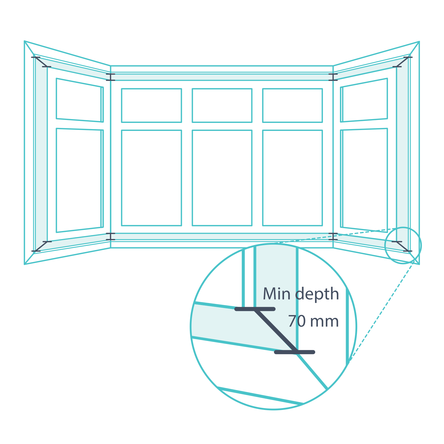
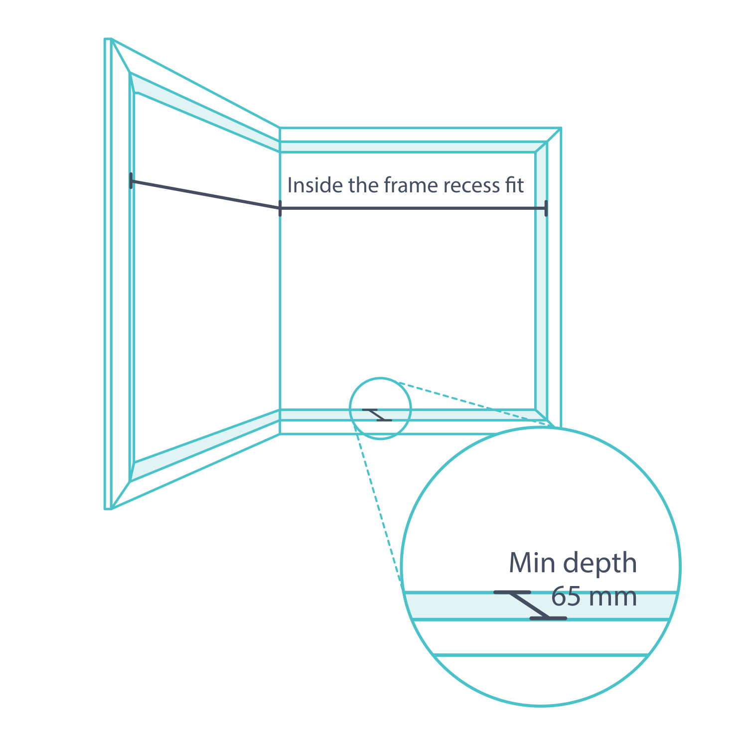
Measure at the front of the recess where the inside L-frame will sit, not back at the glass. Aim for 70 mm of usable depth. Where hardware reduces that space, complete the detailed L-frame obstruction checks before taking final widths.
1. Measure the left bay face
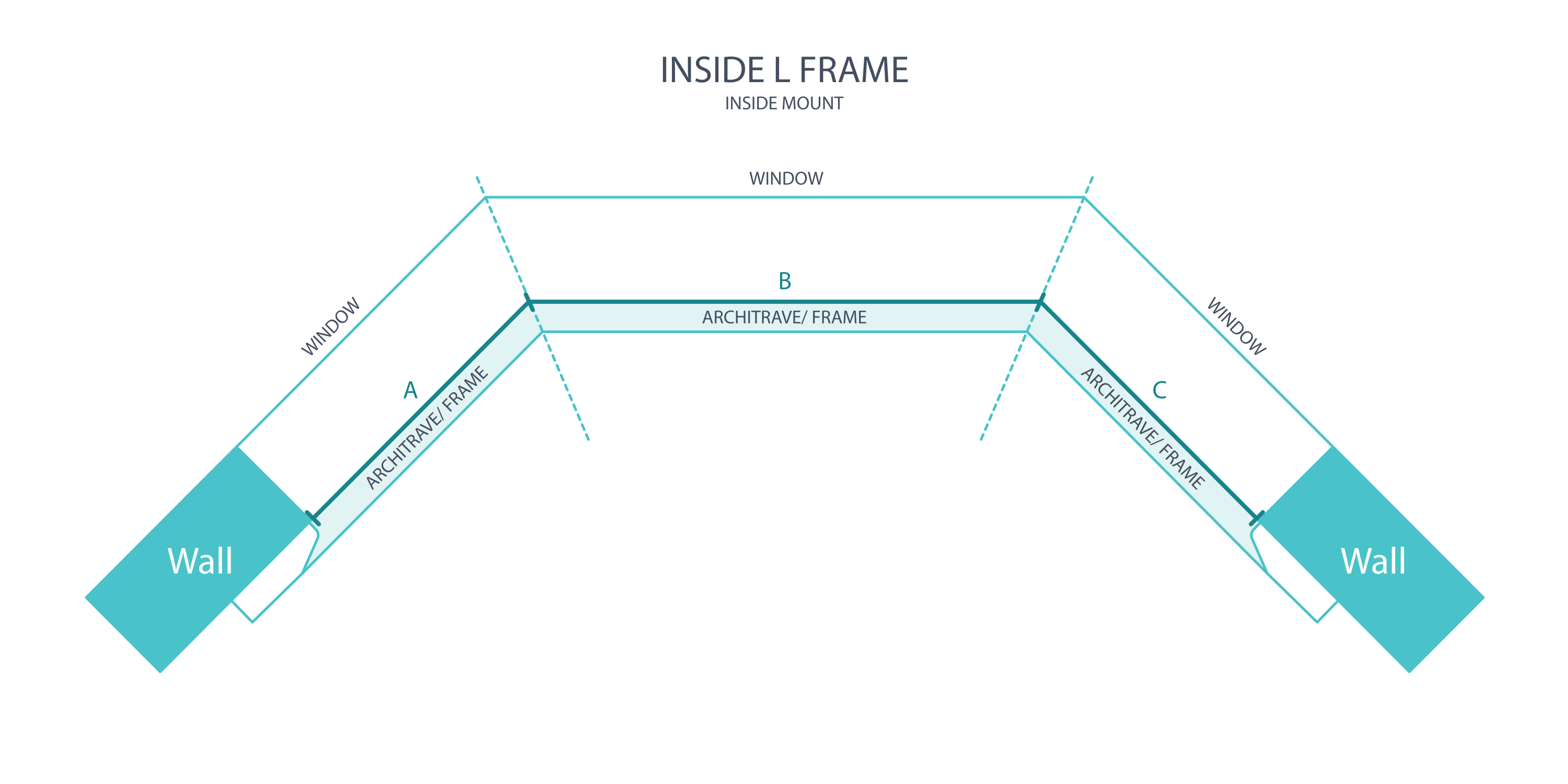
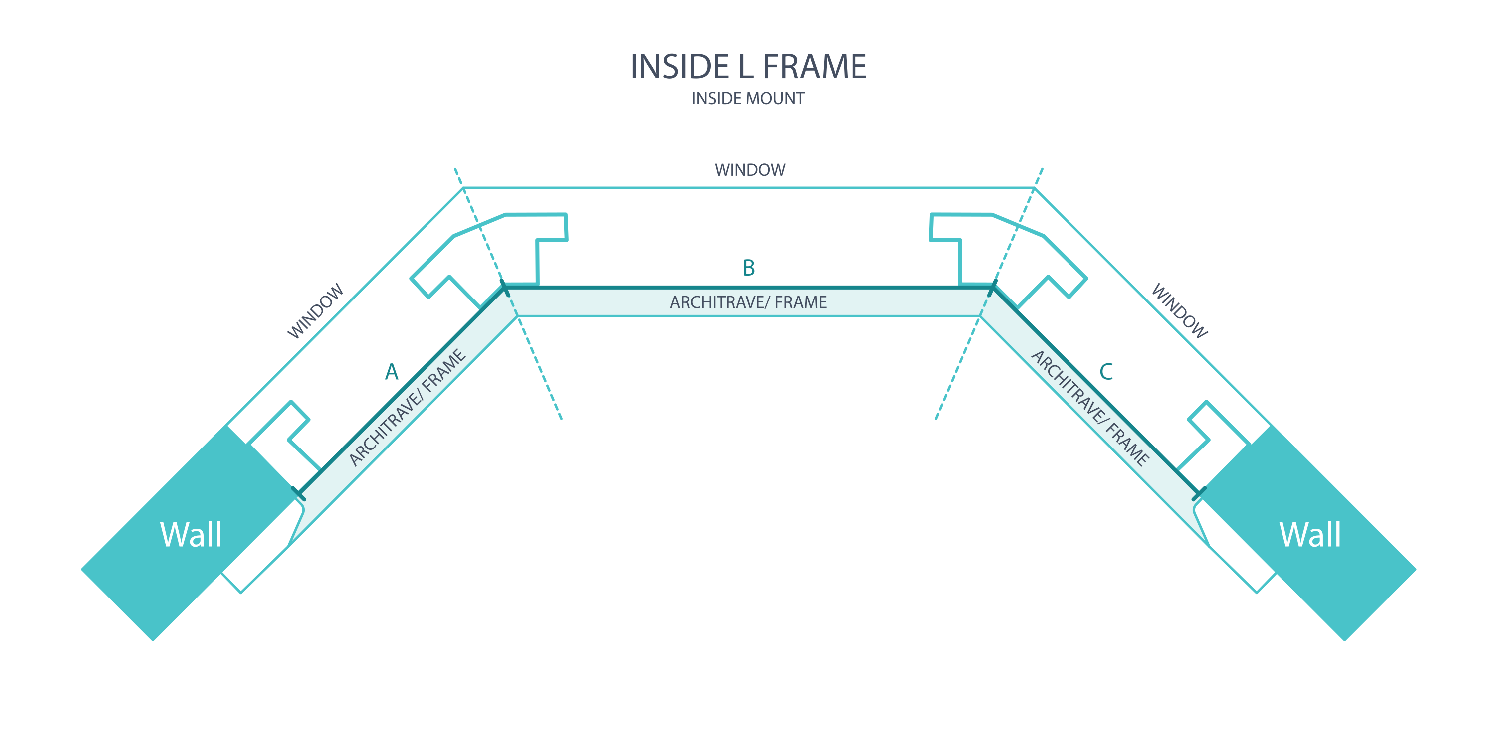
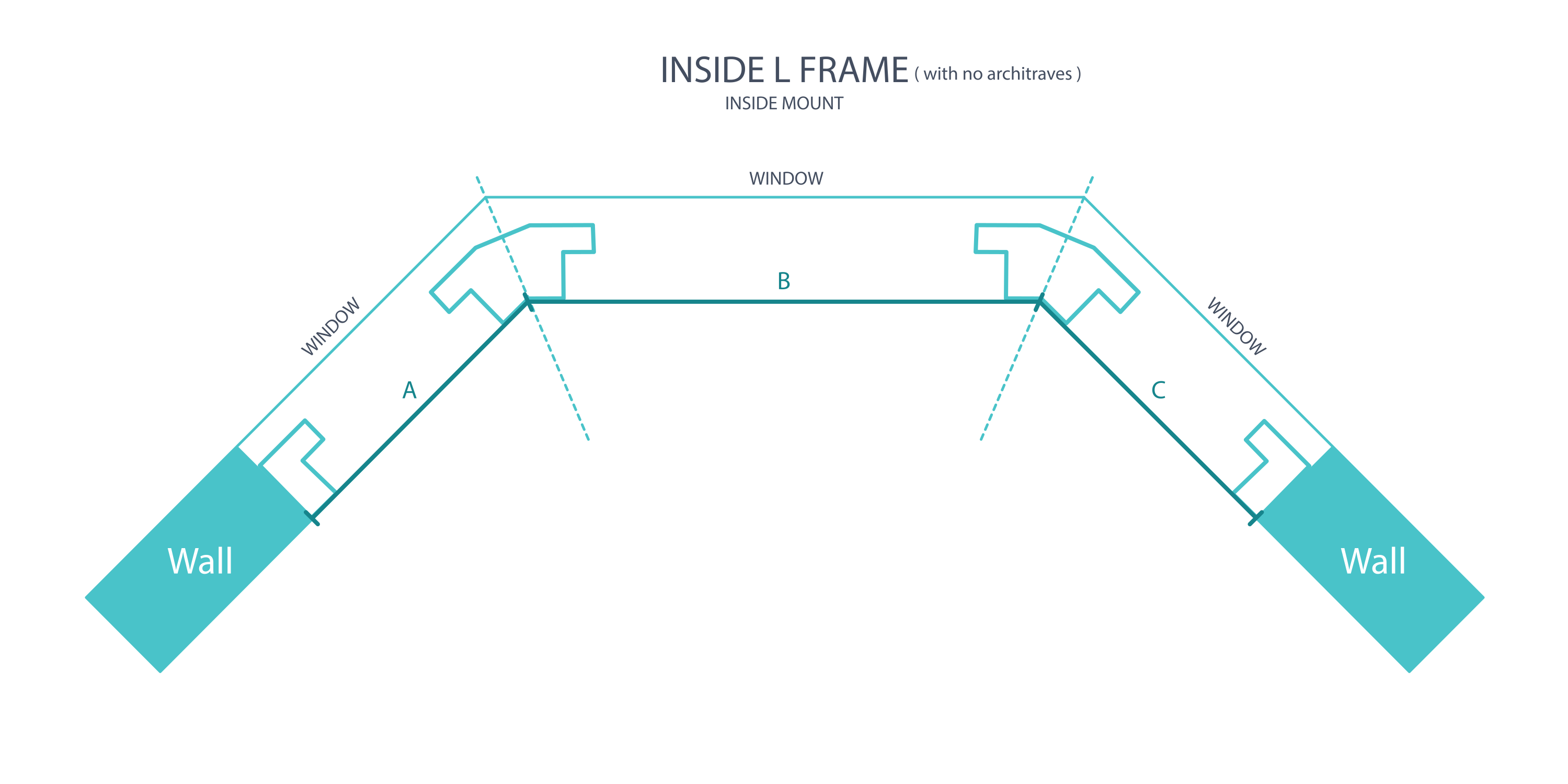
At the intended inside L-frame plane, measure the left opening edge to the first confirmed bay junction, A–B. Take top and bottom readings and use the smaller width. Follow the diagram matching your trim and sill.
2. Measure the centre and right bay faces
Measure the centre face B–C between the two confirmed bay junctions, then the right face C–D from the second junction to the outer opening edge. Take top and bottom readings for each and retain the smaller width. Record all three faces separately.
3. Measure the drop
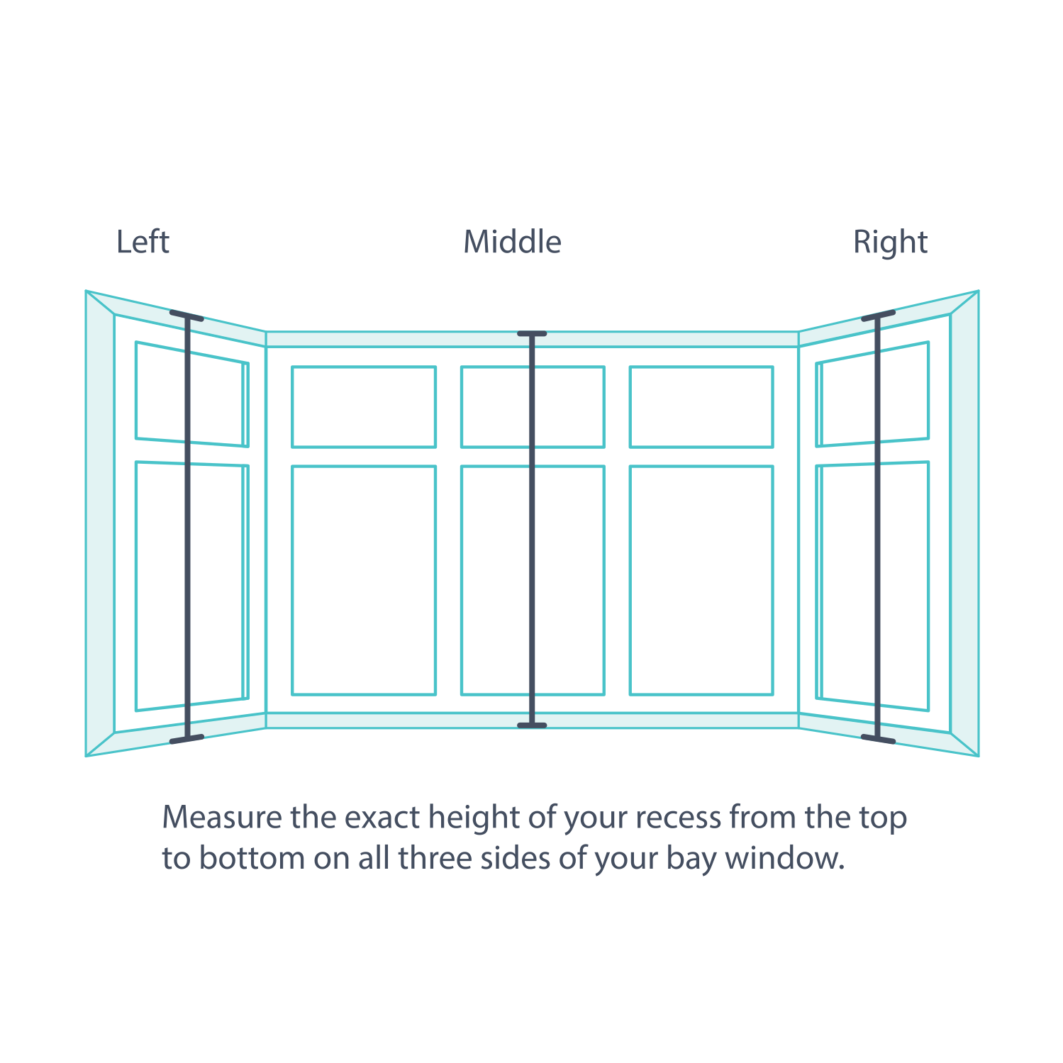
Check the drop at three positions across each face. Keep the readings with that face's label so the left and right figures cannot be mixed up.
4. Record the smallest drop
Use the smallest of the three drops for each recess-mounted face. Enter the measured value without subtracting a manufacturing clearance.
Windows With a Sill or Full-Length Windows
A projecting sill or full-height opening can hide the simple corner reference. Establish where the two proposed frame planes meet before measuring either face. For a floor-length opening, use the floor as the lower working surface in the following string method.
1–4. Establish each bay junction
Use straight strings to extend the proposed frame planes through the first bay junction as illustrated. Their intersection establishes that measuring reference. Repeat at the second junction. On a full-height opening, use the floor as the lower working surface.
5. Check both junctions
Check the clearances around each string intersection shown in the drawings. Adjust the lines until they describe the intended frame planes consistently. Confirm both junctions rather than assuming a symmetrical bay.
6. Record all three widths
Use the confirmed first and second junctions for the inside L-frame widths: A–B left, B–C centre and C–D right. Keep the measurements on one mounting plane and retain the smaller top/bottom reading for each face.
7. Submit the bay plan
Send the three labelled face widths, drops, both angles and photographs together. Include the sill and obstruction details. Have the bay-post arrangement confirmed before entering a custom order; do not treat the centre face as an independent rectangular shutter.
Measuring for an Inside Z-Frame
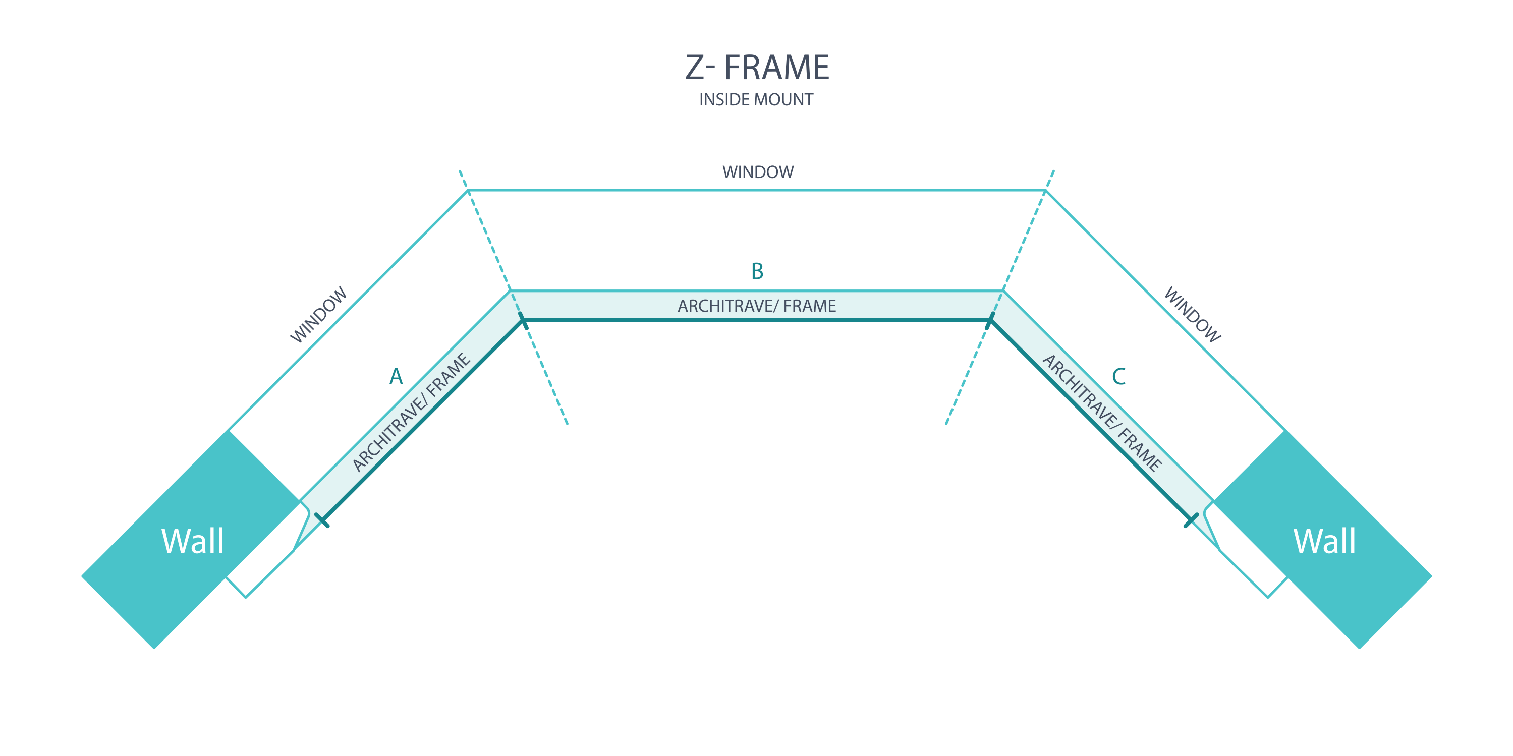
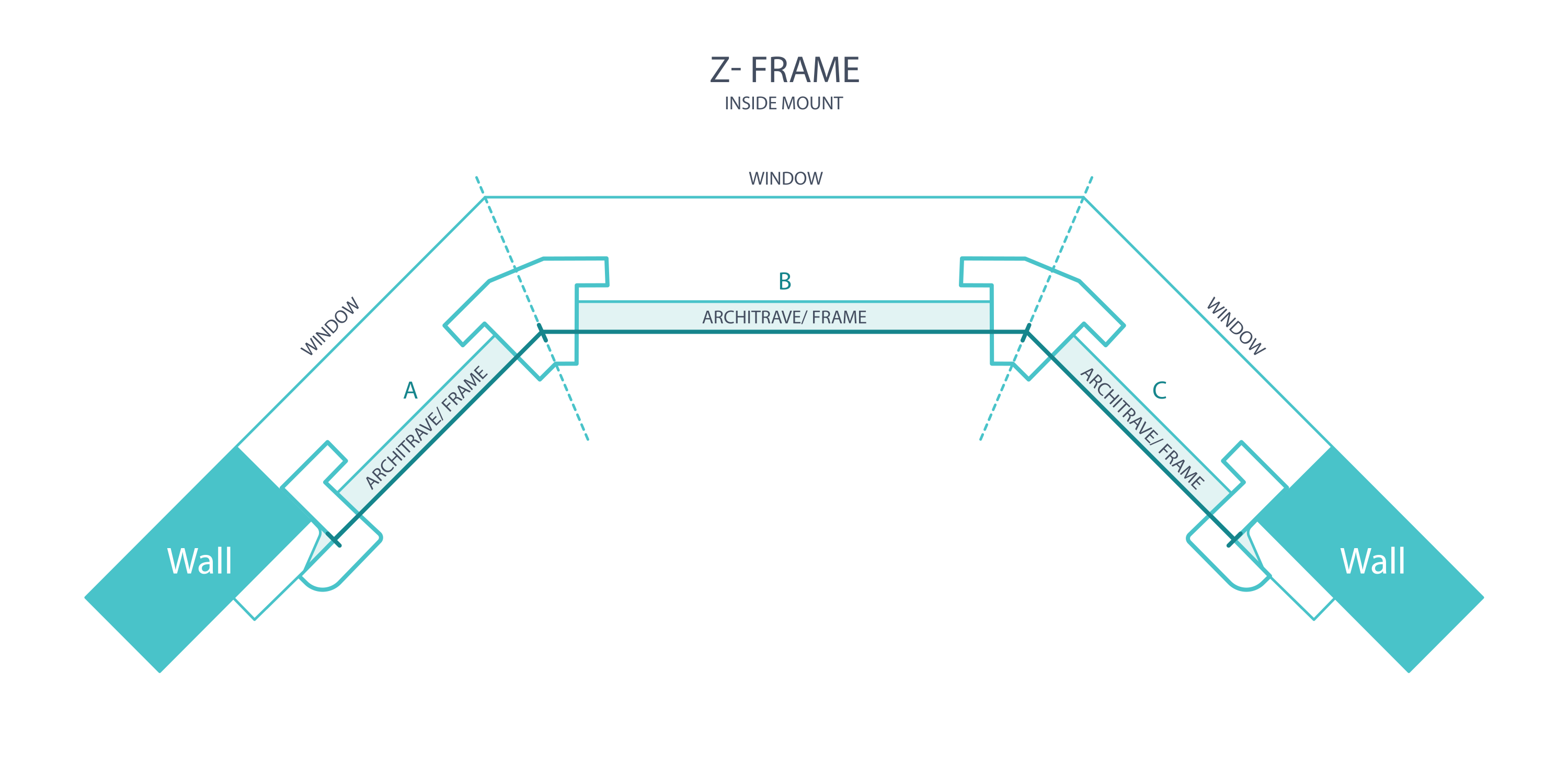
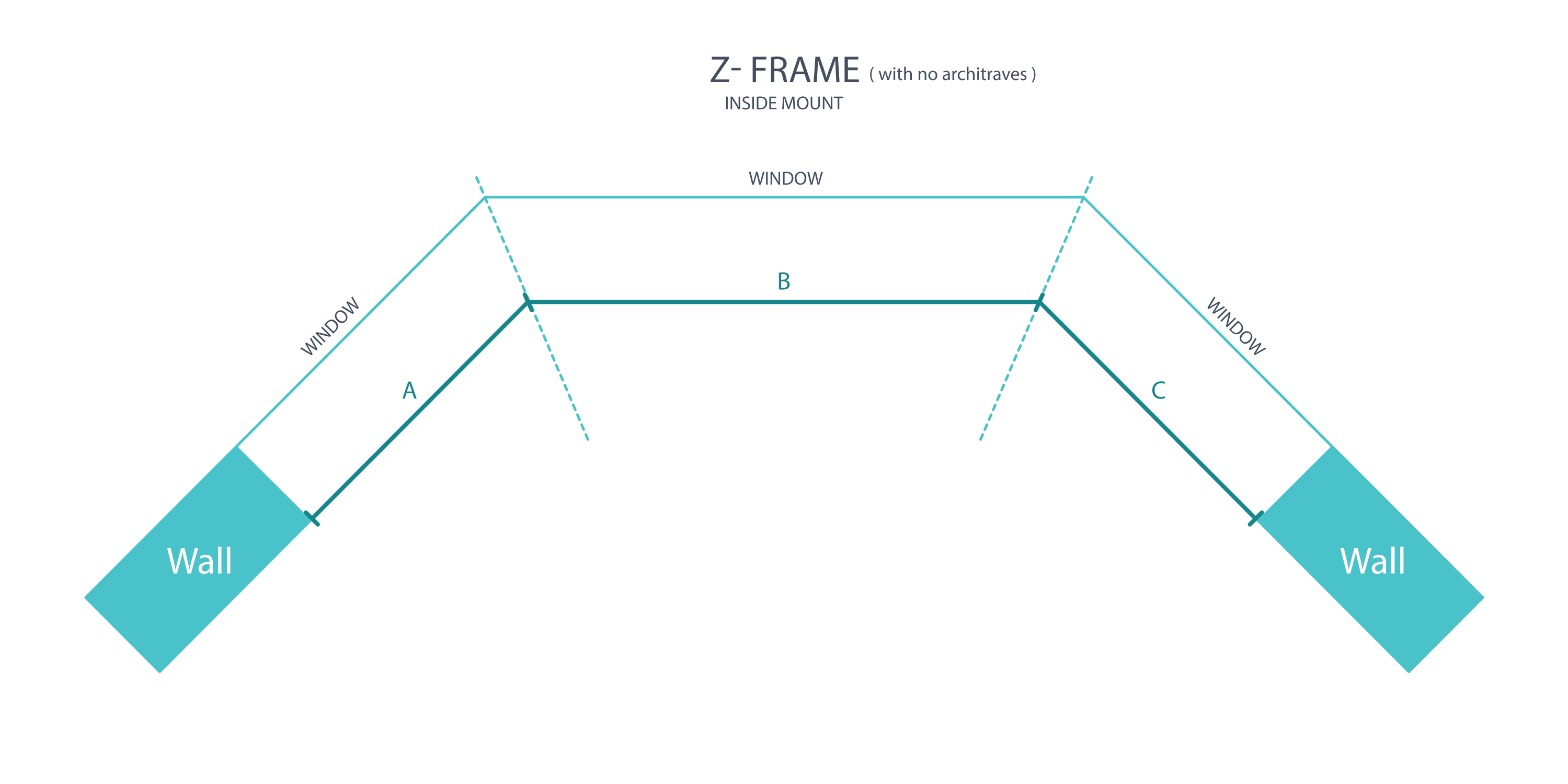
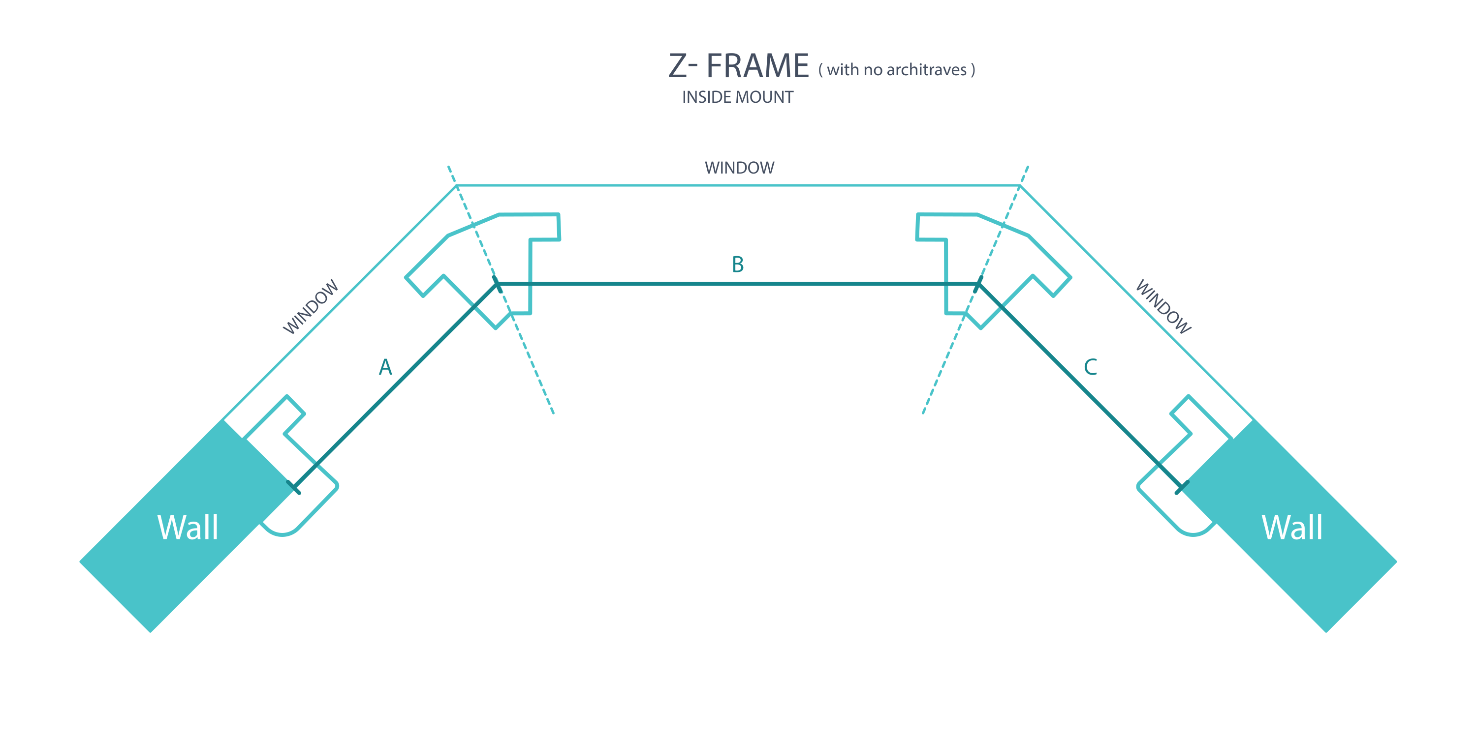
Use the Z-frame drawing to establish the corner reference at the front edge and lip; do not automatically reuse an inside L-frame intersection. The reference corner method allows approximately 65 mm of clear depth. Check any tighter condition against the Z-frame's blade and fixed-component clearances before proceeding.
1. Measure the left Z-frame face
Use the Z-frame lip and front-edge reference in the matching diagram. Measure the left outside end to the first confirmed bay junction, A–B. Check top and bottom and record the smaller width.
2. Measure the centre and right Z-frame faces
Continue on the same Z-frame reference plane: B–C between the junctions for the centre and C–D to the outer right end. Take top and bottom readings on each face and use the smaller width. The L-frame reference cannot automatically be substituted.
4. Measure the drop
Measure the recess drop at three positions on each face, from its lower reference to the inside top. Use the smallest drop for that face without a manufacturing deduction.
Measuring for an Outside L-Frame with an Architrave
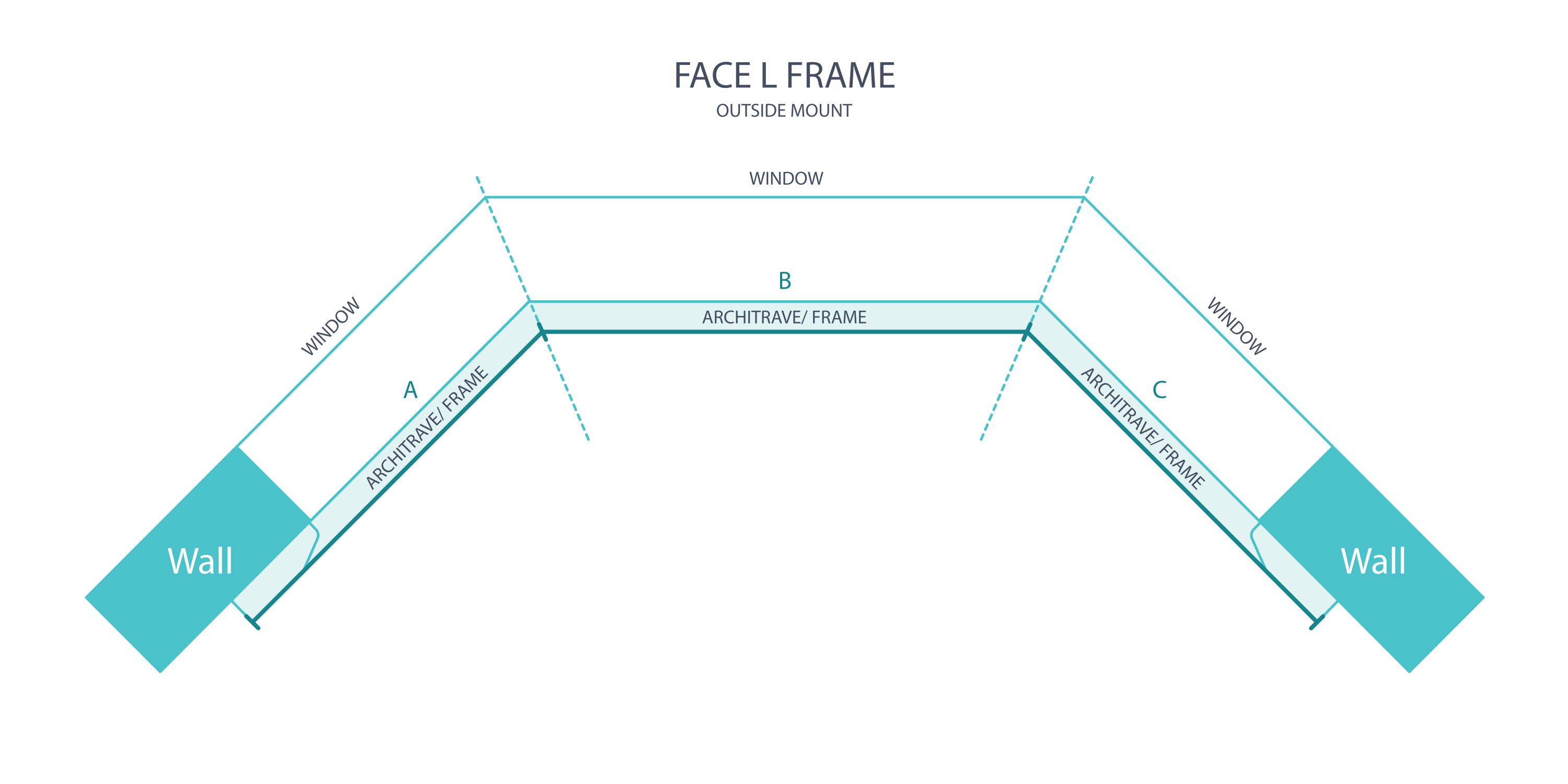
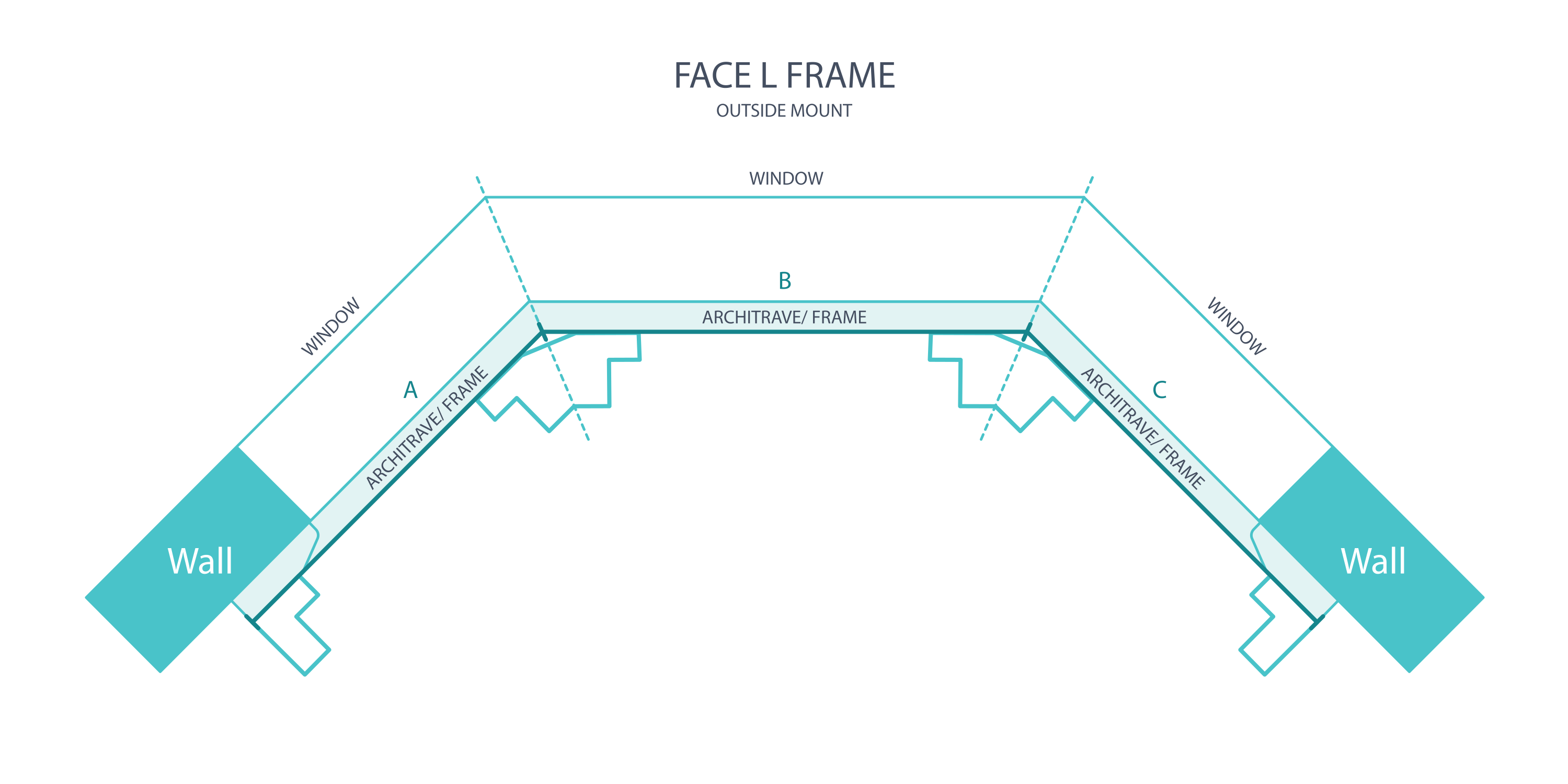
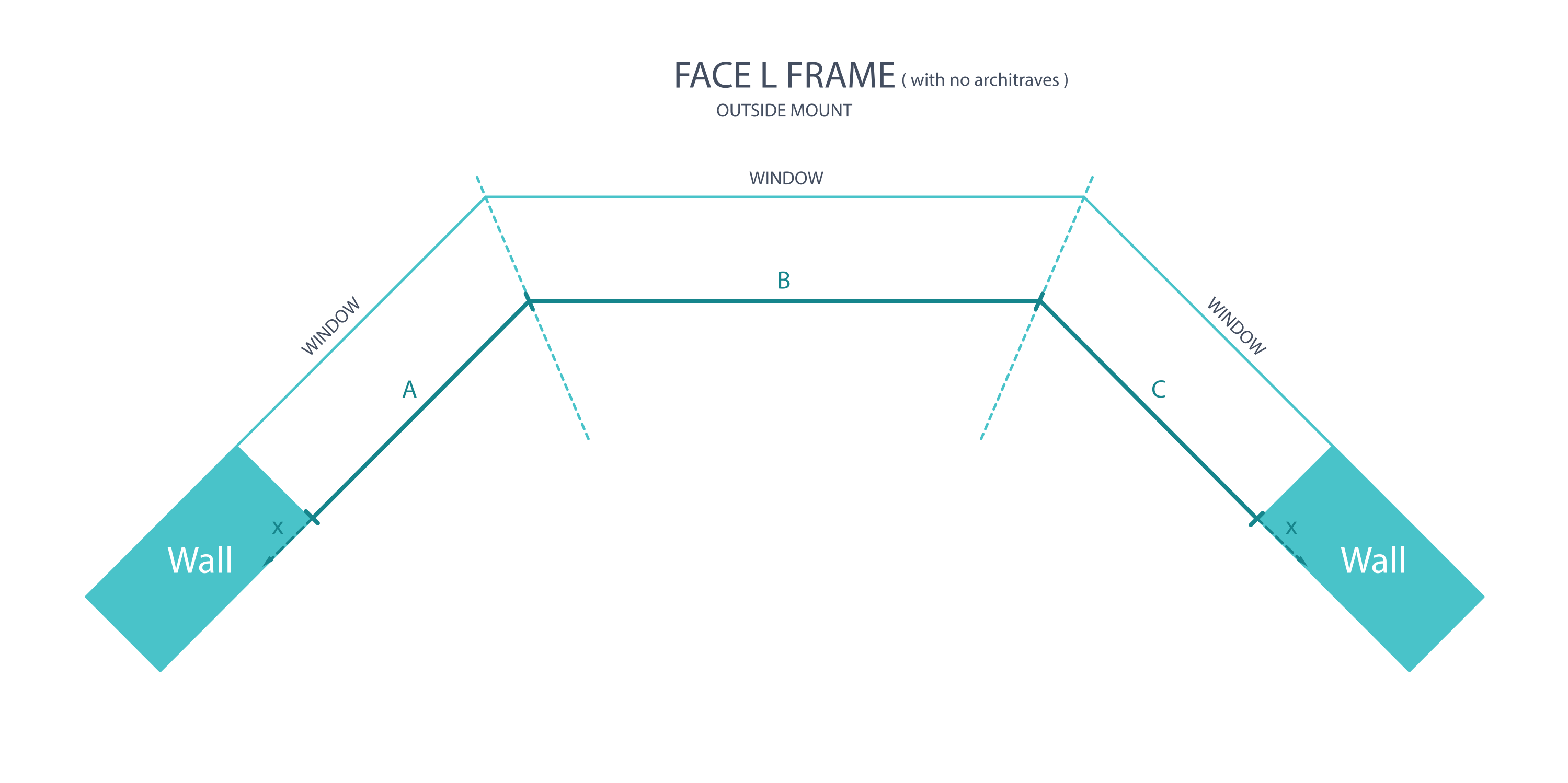
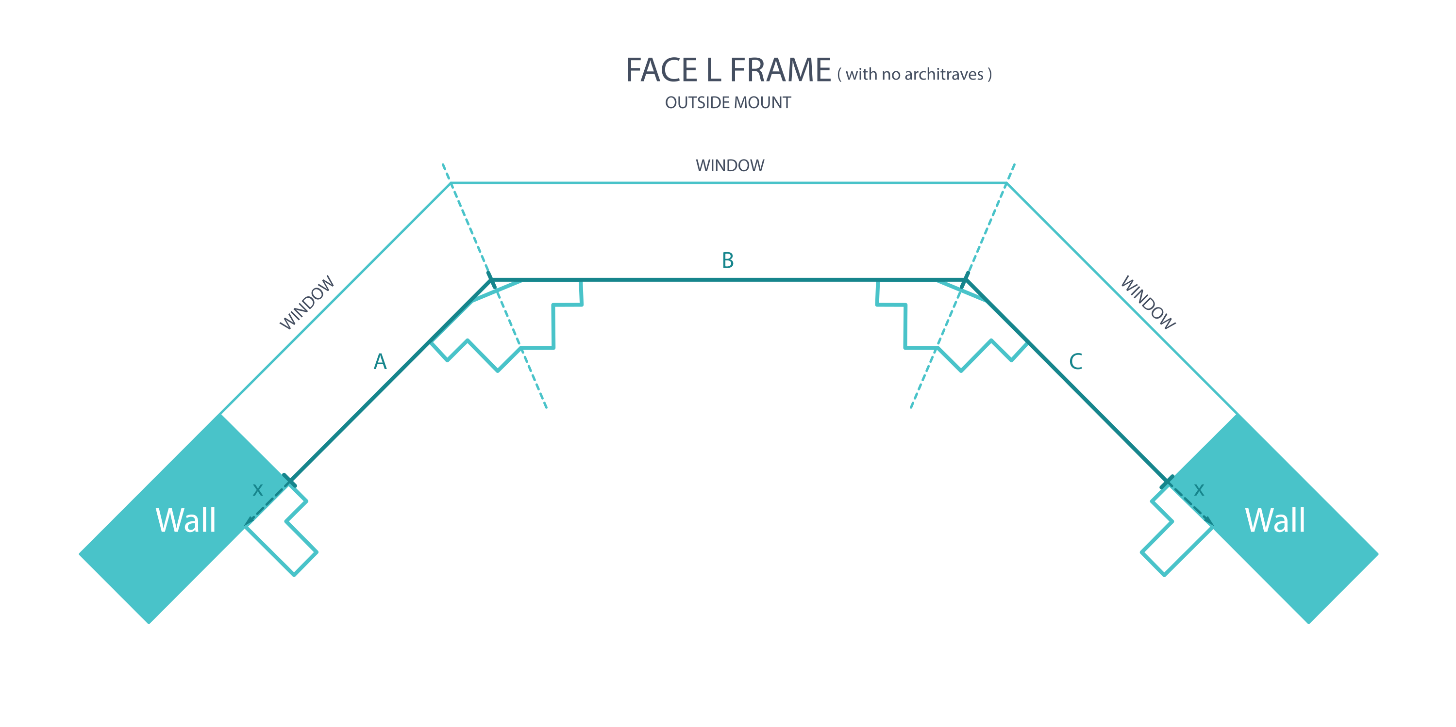
For a face fit over architraves, use the outer trim edges and the junction shown in the drawing. The purpose is to cover the trim fully, so this method selects the larger width and drop readings.
1. Measure the left face over its architrave
Measure from the exposed outer left trim edge to the first confirmed bay junction. Take top and bottom readings and retain the larger width so the trim is covered.
2. Measure the centre and right faces over trim
Measure the centre between the two bay junctions, then the right junction to the exposed outer right architrave edge. Check top and bottom and use the larger width for each face. Keep both shared junctions consistent with the bay-post plan.
3. Measure drops over the architraves
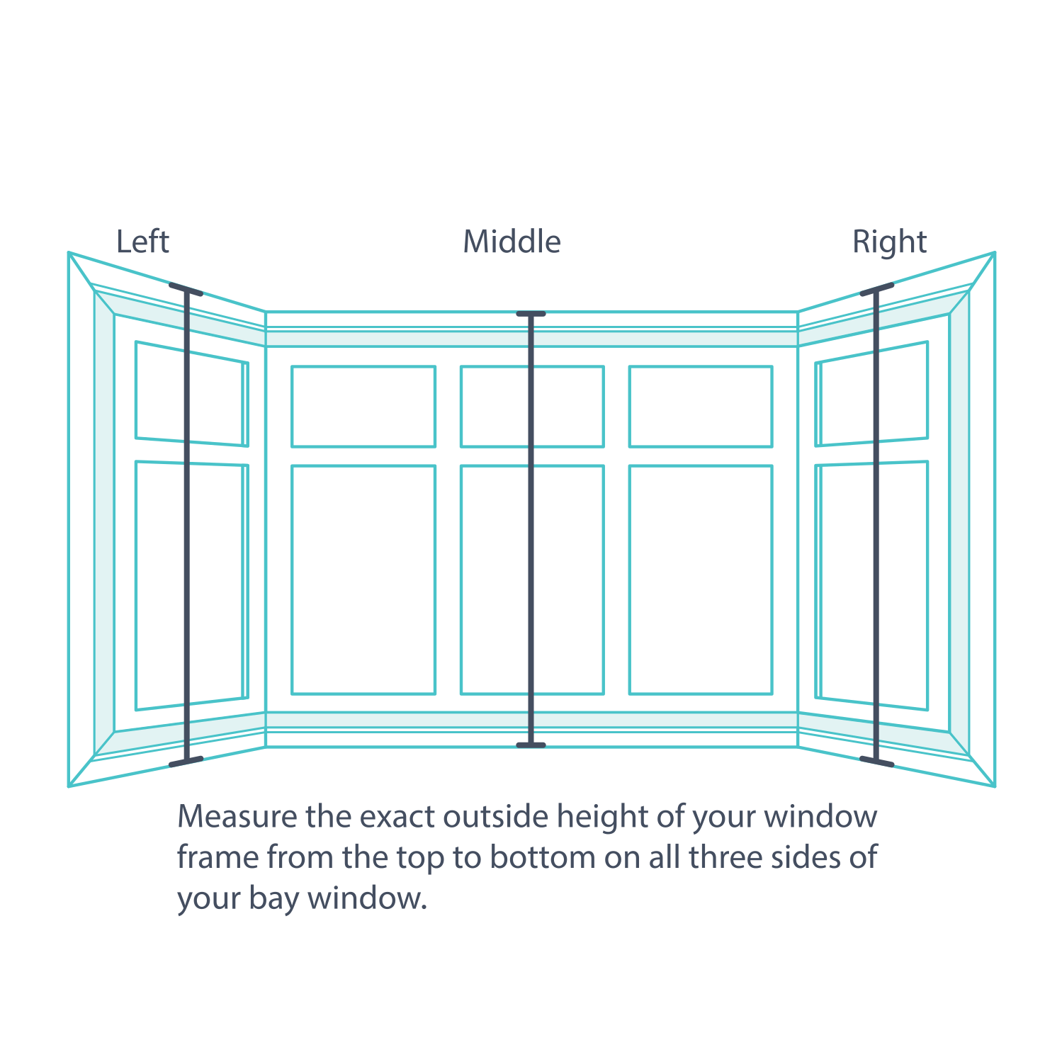
On each of the three faces, measure from the outside bottom trim edge to the outside top trim edge in three places. If a sill changes the lower boundary, record that detail for review.
4. Record the largest drop
Use the largest of the three architrave-to-architrave drops for each outside-mounted face. This differs from the smallest-drop rule used within a recess.
5. Submit the three-face arrangement
Keep the left, centre and right dimensions together with the bay angles and trim photographs. Have the post positions and final outside-frame boundaries confirmed before ordering.
Measuring for an Outside L-Frame for a Square Set window
A square-set corner has no architraves. Measure the opening faces at the specified corner references, then add the frame allowance only at the exposed outer ends. Do not add a second outside-edge allowance at the shared corner post.
1. Record the left square-set face
Measure the left opening face to the first bay junction at the top and bottom. Record both figures and identify the exposed outer edge. The illustrated outside-frame allowance is 42 mm at an exposed edge; do not add that allowance again at a joining post.
2. Record the centre and right square-set faces
Measure the centre between the two junctions, then the right face from its junction to the exposed outer opening edge. Record the top and bottom readings for each. The centre has a joining post at both ends, so have its finished width confirmed with the full bay plan rather than applying a two-window corner formula.
3. Measure all three opening drops
Take three drops on each bay face. Keep the top and bottom reference surfaces consistent and note any projecting sill.
4. Check vertical frame coverage
For the illustrated outside frame without a projecting sill, top and bottom coverage adds 84 mm to the selected opening drop. A projecting sill changes that bottom detail. Include all three sets of readings so the final arrangement can be confirmed together.
5. Confirm allowances before ordering
Submit the complete three-face plan before entering final order dimensions. Confirm both bay posts, the centre face, exposed end allowances and sill treatment. This avoids transferring a two-face corner allowance to the three-face bay.
Shutter Panels
Plan the panel divisions with the existing glass layout. Openings above roughly 950 mm generally need more than one panel; an individual panel can be approximately 900 mm wide plus its surrounding frame contribution. Double-hinged layouts have tighter limits.
What if the window panes are uneven?
Use custom T-post centres where unequal panes would otherwise put the shutter joins across clear glass. Check each resulting panel width against the selected configuration's permitted dimensions.
Multiple panels across a bay
Each bay post occupies space at a junction. Equal panels can work where exact alignment is unnecessary; custom T-post positions can follow unequal panes. Check the panels adjacent to both bay posts and the centre face, where the two junctions affect the available width.
Measuring custom T-post locations in a bay
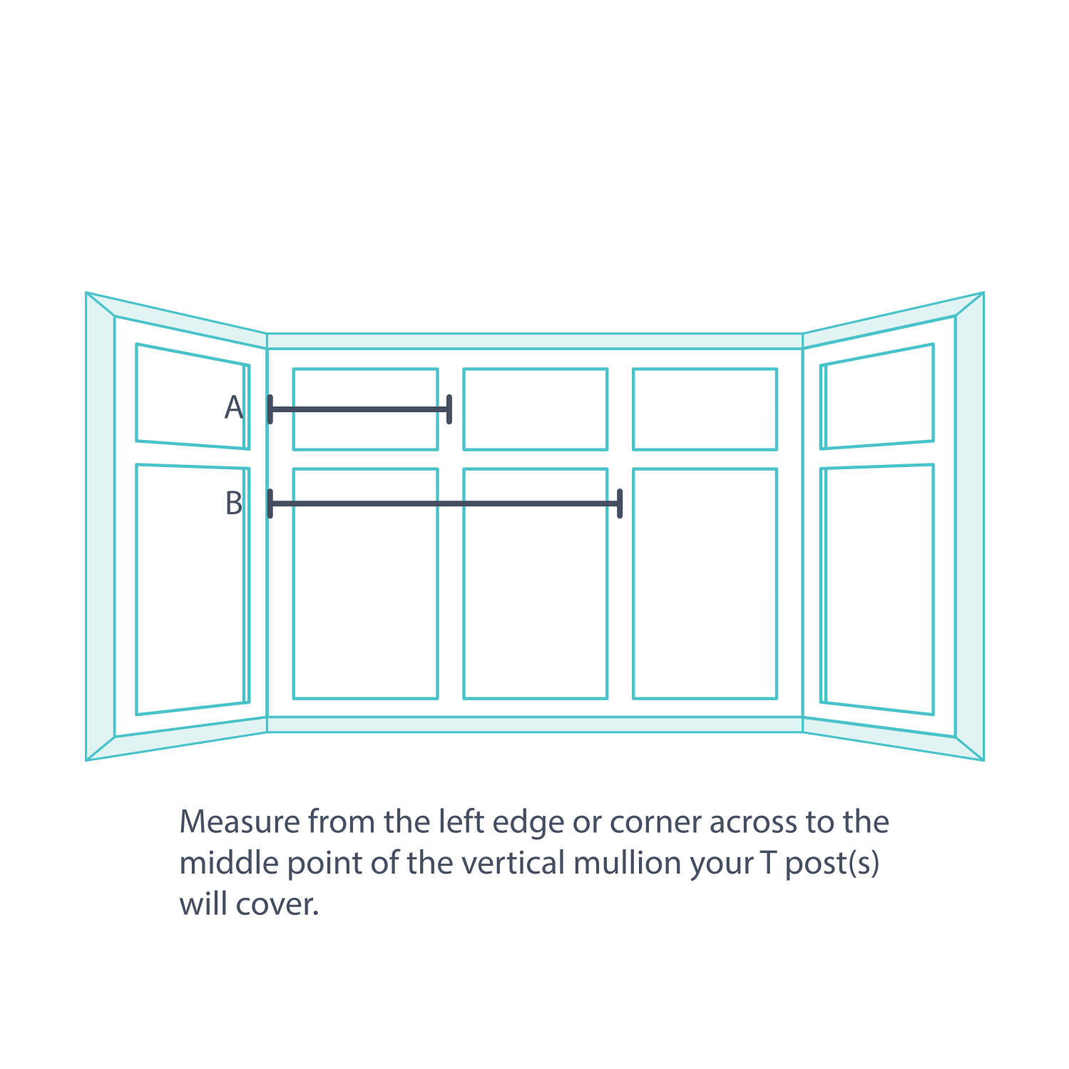
Measure each T-post centre cumulatively from the confirmed left-hand frame reference for that face. Label the readings Left, Centre or Right. Use the agreed mount and bay-post plan to establish those starts; never measure individual panel widths from one join to the next.