Choose the product and mounting method, then work through the steps in order. Dimensions are in millimetres. Keep the raw readings, final order size and window label together.
Before you measure
Prepare your measurements
Use a metal tape and record exact millimetres, width first and drop second. Measure each opening separately, even when windows appear identical. Work at the finished window rather than using building plans or old blind dimensions. Recheck every figure before ordering.
Choose the fixing position
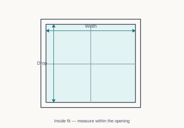
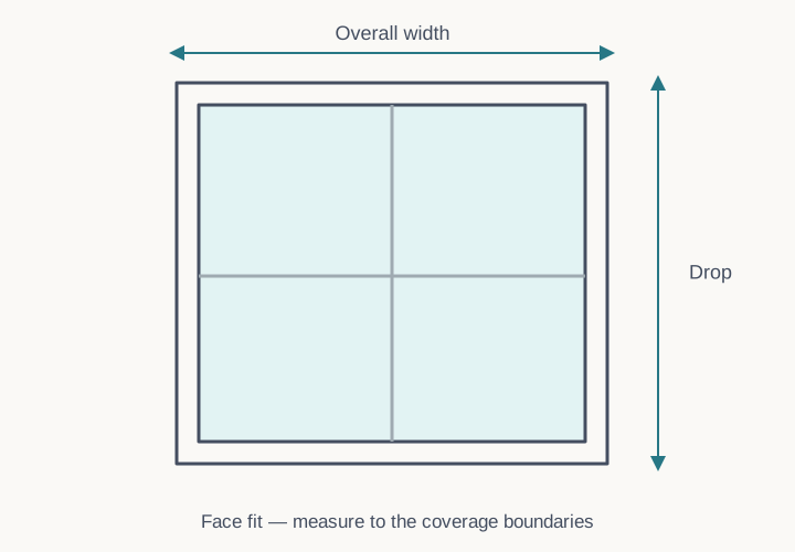
Identify sound support for the brackets or frame. Check handles, winders, screens, tiles, cornices, sills and furniture, including the movement of the window. Recess fit sits within the opening; face fit fixes to the trim or wall in front. Read the full method for your product before applying allowances.
Record the opening and the order size
Keep the raw readings and the final order dimensions on the same labelled worksheet. Apply only the additions or deductions specified for that product and mount. Standard recess fitting allowances are made in manufacture. Face-fit dimensions normally describe the finished coverage, including the stated hardware.
Curtains and curtain tracks
Choose your curtain arrangement
Use the dedicated guide for a single curtain or lining, double curtains, box and bay windows, or a curved track. These instructions are for curtains supplied with a new track. The online curved-track arrangement covers 90° bends with up to two corners; other shapes need a checked plan.
Work through the matching guide
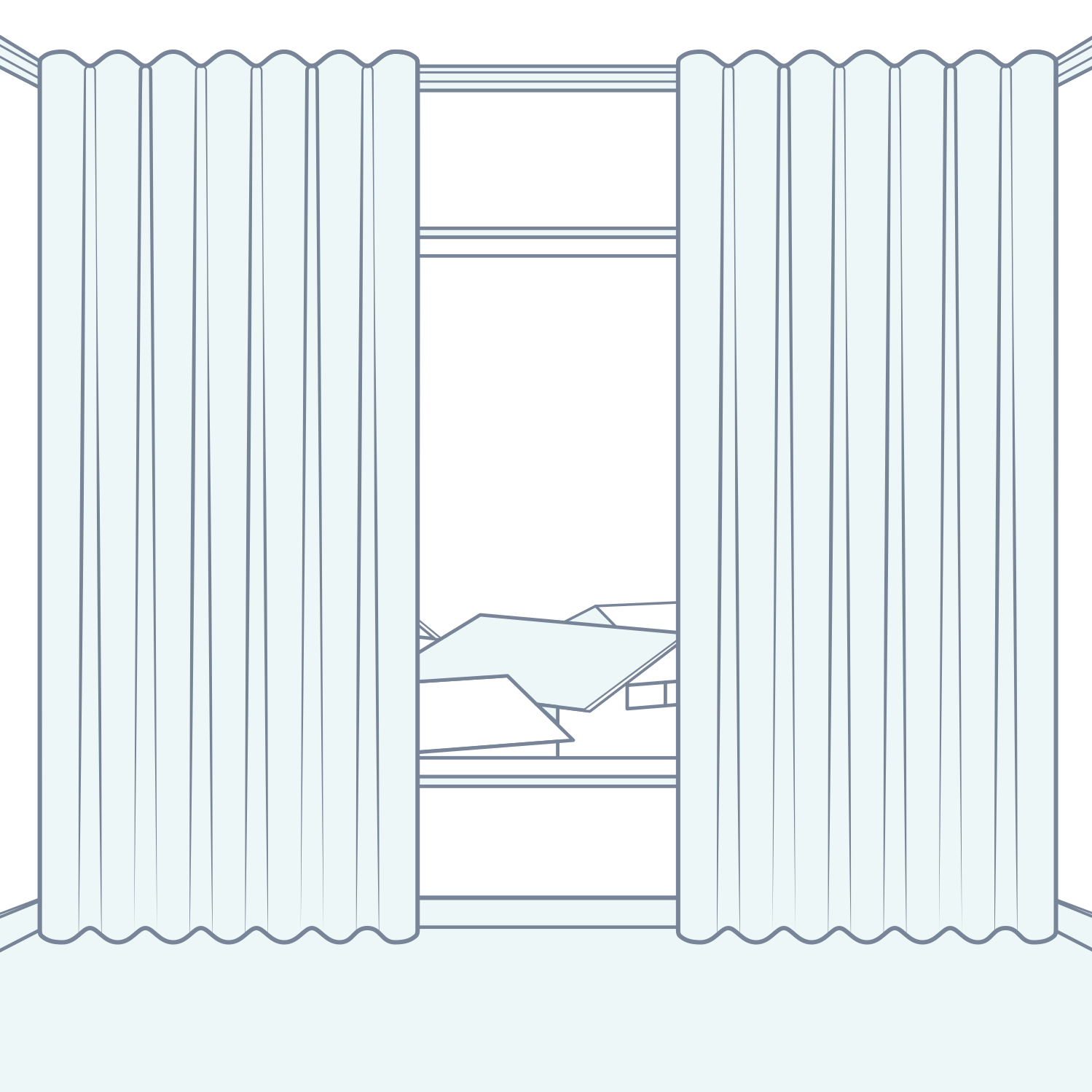
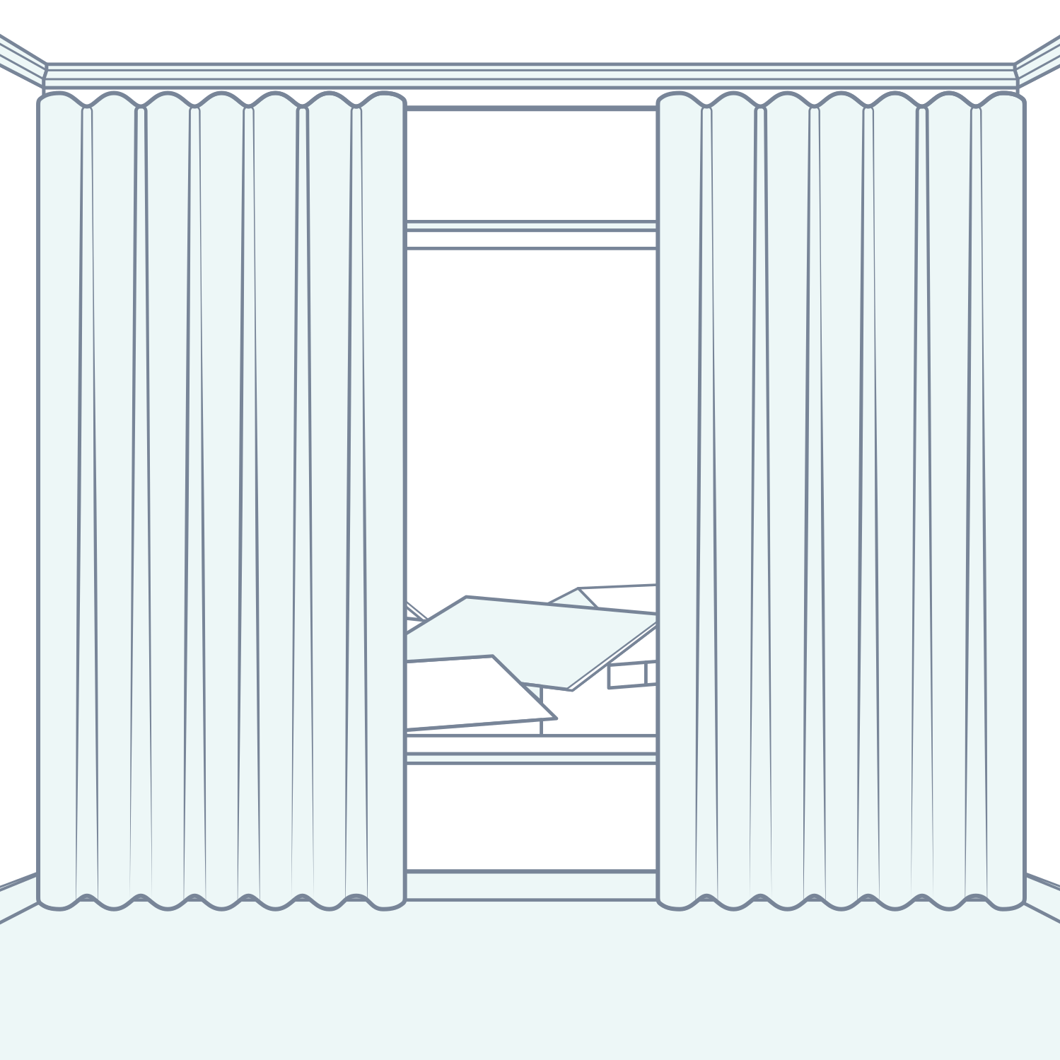
Choose ceiling or wall mounting before recording width, custom split positions, drop and floor finish. Track width is different from fabric fullness. Measure drops from the specified track reference and let the selected floor finish determine the manufacturing adjustment.
Plantation shutters
Choose the frame and mount
For an inside Z-frame, allow 60 mm of clear depth and room for its 19 mm front lip. An inside L-frame needs 70 mm of blade clearance. Z-frames suit many square-set, square and bullnose openings; detailed architraves need their lip position checked. With a projecting sill, specify the bottom detail so a three-sided Z-frame can finish with an L-section on the sill.
Check hardware and the fixing surface
Measure to the nearest obstruction, not only to the glass. A central winder may fit behind an aligned midrail with 30 mm from its tip to the recess front; submit photos where a cut-out or special arrangement may be needed. The detailed shutter obstruction guide separates fixed-frame, rail and rotating-blade clearances. The published outside-fit method also requires a usable flat fixing area on the outer architrave corner.
Measure for a recess fit
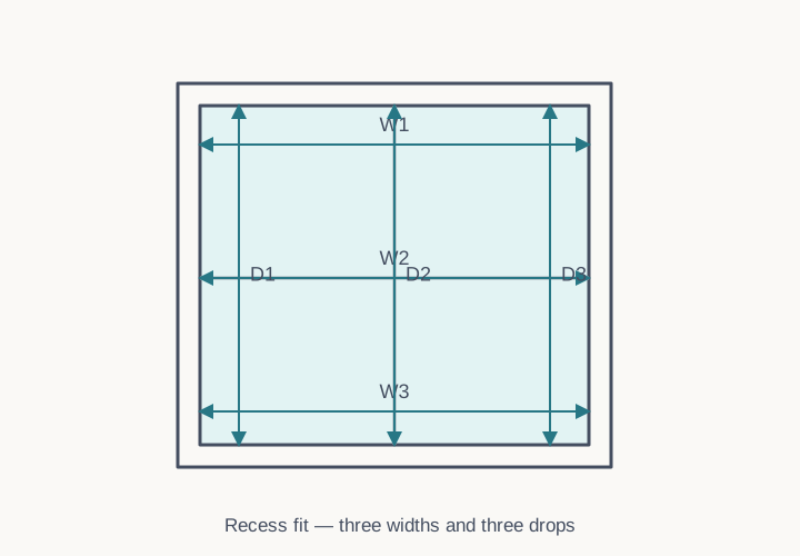
Measure three widths and three drops inside the opening. Use the smallest width and smallest drop and make no deductions. Where a sill projects, measure to its upper surface and select that sill detail. If widths or drops vary by more than 6 mm, an inside L-frame is unsuitable; over 12 mm variation rules out a Z-frame. Have uneven openings checked before ordering.
When the recess is tight
An inside L-frame can sometimes move forward 5–10 mm or more if it can still be securely fixed. For a bottom winder, the published frame-depth checks are 50 mm for an L-frame or 40 mm for a Z-frame; blade clearance remains a separate check. Do not choose a shallower arrangement without checking the complete frame, panel and hardware movement.
Face fit over an architrave
Measure three widths across the outer trim edges and three drops between its outer top and bottom edges. Use the largest readings so the shutter covers the architrave. A projecting sill becomes the lower surface. Decorative trim needs a continuous flat fixing plane; use the detailed frame guide before choosing that boundary.
Face fit without architraves
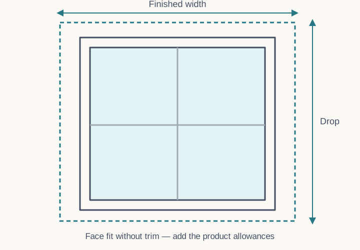
Measure the opening in three places each way and use the smallest width and drop under this My Direct method. Add 42 mm at each edge: 84 mm overall to the width and 84 mm to the drop. With a projecting sill, add at the left, right and top only: 84 mm width and 42 mm drop. Do not add material below the sill.
Special shutter arrangements
The standard online method is for interior window shutters. Send bay, corner and sliding-door arrangements to the team for confirmation. Fixed U-channel installations use top and bottom channels and do not provide folding panels; they need 45 mm of fixing surface. Use the separate shutter guide for panels, T-posts, midrails and detailed illustrations.
Single and double roller blinds
Choose recess or face fit
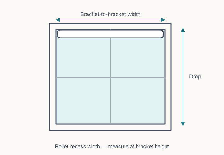
A recess fit leaves the trim visible and keeps the blind within the opening. A face fit can improve edge coverage and clear obstructions in the reveal. Order width is measured from bracket to bracket, not across the fabric. Select roll direction and check both fabric paths for double blinds.
Check recess depth
For a single over-roll, 70 mm lets the blind sit within the recess. A single under-roll needs 45 mm from the nearest obstruction, although the tube may project. For the slimline double bracket, allow 90 mm for over-roll within the recess, or 70 mm from the nearest obstruction for under-roll, with possible tube projection.
Recess width and drop
Measure the width at the top of the recess, where the brackets fix. Measure the drop from the inside top to the sill. Keep the tape vertical and do not subtract factory allowances. If tiles narrow the opening, record the top and tiled widths: use the top when the total reduction is less than 24 mm and the narrower tiled width when greater than 24 mm. Ask us to check an exact 24 mm reduction.
Face fit with an architrave
Measure the outer trim width at the top fixing position. Measure from the top of the architrave to the intended bottom finish. For a shorter window, extending 100–200 mm below the sill can improve coverage where there is space. Under-roll normally brings the fabric closer to the wall.
Face fit without an architrave
Add at least 100 mm overall to the opening width. After allowing for the hardware, this provides approximately 35 mm of fabric overlap per side. Measure the required drop and add at least 100 mm above the opening for the fixing position. Check that the wall is clear and can carry the brackets.
Two separate layers and light gaps
For two single blinds with one in the recess and one on the face, the recess blind needs 70 mm to sit fully inside in the published arrangement. Hardware leaves a fabric gap of around 20 mm at the chain end and 10–20 mm at the pin end; an uneven opening can increase it. Blockout fabric does not seal those perimeter gaps.
Full-enclosure cassette roller blinds
Recess dimensions
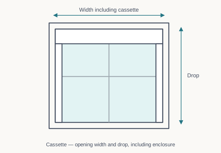
Measure three widths and three drops and use the smallest of each. Supply the same opening dimensions for the compatible blind and cassette. Make no deductions. Allow at least 50 mm from the nearest obstruction; the headbox can project if the recess is less than 90 mm deep.
Check the perimeter
Installation can leave a gap of approximately 2 mm or more between the enclosure and the opening. Suitable silicone or quad can finish this perimeter where appropriate. Confirm the surfaces are suitable before planning a sealed light-control result.
Face fit and compatibility
Over trim, use the compatible roller face-fit method and avoid profiles that prevent the enclosure sitting flush. Without trim, allow 101 mm above the opening and at least 50 mm at the left, right and bottom. For a top-and-sides arrangement, extend the drop only as needed. A projecting sill can prevent the intended enclosure fit. Order the compatible under-roll blind and cassette together; this is not a retrofit enclosure for an existing blind.
Linked blinds and wide sliding openings
Plan the joins
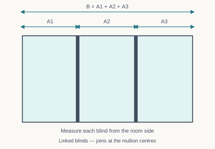
A single roller blind is limited to 3000 mm in this arrangement. Linked blinds can reduce a meeting gap to about 17 mm compared with roughly 30 mm or more between separate butted blinds. Put joins at mullion centres rather than across clear glass. The online linked system supports two or three blinds; contact us for a larger arrangement.
Measure each face-fit width
For three blinds, measure A1 from the outer left trim edge to the first mullion centre, A2 between the mullion centres, and A3 from the second centre to the outer right trim edge. Check that A1 + A2 + A3 equals the complete span B. The same method uses two segments on a two-panel opening.
Measure the drop and enter the set
For rollers, measure from the upper fixing reference to the intended bottom finish. Romans and Venetians use their own drop and floor-clearance rules. Enter linked pieces separately with Left, Middle and Right labels under one room name. Keep their controls and motor arrangement consistent; where the selected linked motor option divides its price between pieces, choose the matching option on each.
Recess mounting
Use inside opening edges and mullion centres instead of outer trim edges. Check the product's depth requirements and leave the normal factory deduction to us. Recess fitting within a sliding-door opening is generally unsuitable because operating space is limited; confirm the layout before ordering.
Bonded and padded pelmets
1. Measure the width
Over a recess blind with architraves, measure the outer trim width and add 60 mm: 30 mm beyond each side. Without trim, add the same 60 mm to the opening width. Over a face-fit blind, measure its bracket-to-bracket width and add 60 mm. Check that the returns clear the trim and there is room for both outer extensions.
2. Select the projection
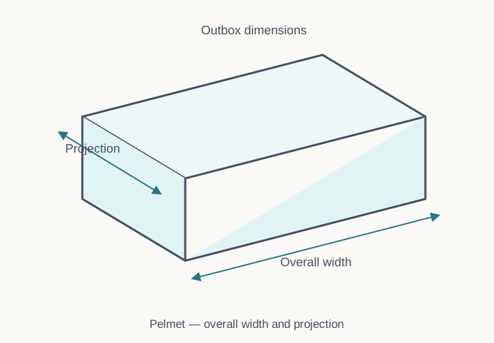
Projection is an outbox measurement from the wall into the room. The roof sits over the architrave and the returns pass around it. The standard recommendations assume the trim projects 20 mm from the wall. If it projects further, choose the next suitable size or request a custom projection, such as 130 mm. Use a consistent projection for neighbouring pelmets where possible.
Projection options
80 mm: recess-fitted blinds. 100 mm: a more generous recess cover or face-fit 25 mm aluminium Venetians. 120 mm: Romans, face-fit single rollers and face-fit Venetians. 150 mm: My Direct double rollers or a single face-fit curtain track. 200 mm: face-fit verticals, double curtain tracks or panel glides. Check other suppliers' hardware against its actual projection.
Timber and PVC Venetian blinds
Choose the fit
Recess fit leaves the trim visible; face fit can improve overlap and clear hardware in the opening. Check the full blade and headrail projection, not only the bracket fixing point.
Face fit with trim
Measure the outer architrave width. Take drops from its top to the intended finish at the left, centre and right and use the smallest. For a short window, allow a finish 30–100 mm below the sill where unobstructed. For full-length windows, finish 8 mm above the floor. The face-fit size includes brackets.
Face fit without trim
Add 30–100 mm overall to the opening width. Take three drops from the opening top to the intended finish and use the smallest, allowing 30–100 mm below a short sill or 8 mm above the floor. Add 60 mm at the top for mounting above the opening.
Recess fit
Allow 80 mm of depth to keep the blind within the recess; less depth means it may project. Measure three widths and three drops and use the smallest of each. Make no deductions. Check winders and other hardware; if a folding winder still conflicts, consider face fit.
Fitting beneath a padded pelmet
The blind fixes into the pelmet roof. Request the appropriate recess/top-fix brackets and allow for any increase in mounting height. The pelmet roof is 20 mm thick, so distinguish its internal fixing surface from the outside top when measuring the drop.
Roman blinds
Use a face fit
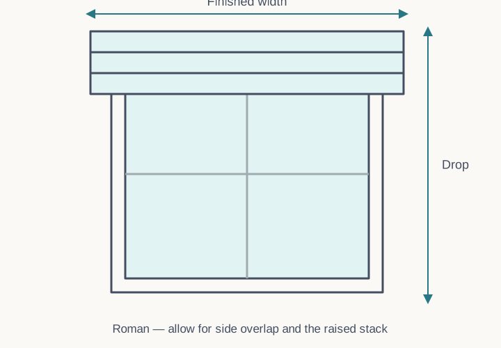
Roman blinds should be face mounted to provide suitable coverage and room for the fabric to settle. Measure the outer architrave width and the drop from its top to the intended finish. Check beds, desks, sills and door-opening clearance.
Allow for the raised stack and side overlap
Add 100–150 mm to the drop so the blind can mount above the architrave and lift more fabric clear of the glass. Add 40–100 mm at each side to the width: 80–200 mm overall. Confirm there is space for these extensions.
Choose the bottom finish and headboard
For a shorter window, finish 50–100 mm below the sill. Leave 20 mm above the floor for a full-length blind, or 30 mm when the drop exceeds 2200 mm. The standard headboard projects 40 mm; choose a larger projection where a sill or other obstruction needs more clearance.
Without architraves
Start from the opening dimensions and apply the face-fit stack and side allowances above. The published no-trim method adds a further 20 mm at each boundary, at least 40 mm extra overall to both width and height. Check the complete intended coverage on the wall before confirming the order.
Vertical blinds
Choose recess or face fit
Face fit is a common choice for verticals because it improves overlap and clears the reveal. A recess fit needs room for the slats to rotate. Check hardware with the window and slats both open and closed.
Recess depth
For 89 mm slats, 100 mm depth keeps the opening slats within the recess; 65 mm is the minimum and allows projection. For 127 mm slats, the corresponding figures are 135 mm and 80 mm. Measure usable depth to obstructions. Check folding winders and access to handles.
Recess dimensions
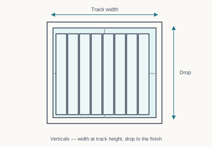
Measure the width at the top of the reveal where the track fixes. Take the drop from the inside top to the sill or floor at the left, centre and right and use the smallest. Make no manufacturing deductions.
Face fit over trim
Measure the outer architrave width, then allow 40–100 mm extra at each side, 80–200 mm overall, where space permits. Measure the drop from the trim top to the intended finish. Without a projecting sill, a short blind can finish 50–100 mm below it; a full-length blind should finish 10 mm above the floor.
Face fit without trim
Add at least 120 mm overall to the opening width. Measure from the opening top to the bottom finish, then add 70–100 mm or more for the intended mounting height above the opening. Check that this wall space is available and suitable for fixing.
Panel glide blinds
Choose face or ceiling fixing
Face fixing directly to an architrave is the standard straightforward arrangement. With architraves present, the standard brackets do not allow a wall fixing above them because they cannot clear the trim projection. Ceiling fixing needs suitable structural support and is often used for full-height room-divider arrangements.
Check the stack space
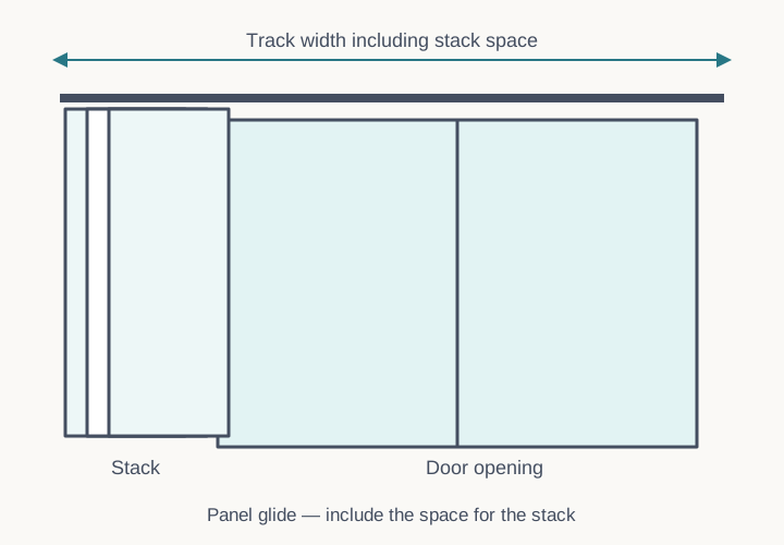
Recess fit is generally not recommended: the stacked panels continue covering part of the glass. Plan which side will hold the stack and whether the panels need to clear the opening completely. Individual panels are typically 500–1000 mm wide.
Measure width and drop
Start with the outside architrave width. Allow at least 300 mm extra on the stacking side and at least 100 mm on the other side. To clear all the glass, the stacking allowance needs to exceed the actual panel width. Measure the drop from the upper fixing reference; finish 50–100 mm below a short, non-projecting sill or 10 mm above the floor.
Calculate the panel width
Panel width = (track width + (number of panels − 1) × 70 mm) ÷ number of panels. For a 3000 mm track with four panels, (3000 + 210) ÷ 4 = 802.5 mm. Use the actual panel width when allowing stack-back space.
Without architraves
Allow at least 400 mm extra width overall: 300 mm on the stacking side and 100 mm on the other. Add 70–100 mm at the top of the drop for the mounting position. Check handles, doors and furniture against both the hanging panels and the full stack.
25 mm aluminium Venetian blinds
Recess fit
Allow 60 mm depth for the blind to sit within the recess. Check obstructions, then measure three widths and three drops. Use the smallest of each without deductions. Less depth can leave the blind projecting.
Face fit with architraves
Measure the outer trim width and take three drops from the top trim to the intended finish, using the smallest. For a short window, finish 50–100 mm below the sill where clear. For full length, finish 8 mm above the floor. The supplied size includes the brackets.
Face fit without architraves
Add 30–100 mm overall to the opening width. Take three drops to the intended finish and use the smallest, allowing 30–100 mm below a short sill or 8 mm above the floor. Add 30–100 mm at the top for the chosen mounting height.
50 mm aluminium Venetian blinds
Recess fit
Allow 70 mm depth, including clearance to handles and winders. Take three widths and three drops and use the smallest of each, with no deductions. If a folding winder still enters the required space, consider a face fit.
Face fit with architraves
Measure outer trim width. Take three drops from the top trim to the intended finish and use the smallest. Allow 30–100 mm below a short sill or 8 mm above the floor. The complete face-fit size includes the brackets.
Face fit without architraves
Add 30–100 mm overall to the opening width. Take three drops and use the smallest, allowing the selected bottom finish. Add 60 mm at the top to mount above the opening.
With a padded pelmet
The blind fixes into the roof of the pelmet, so select the recess/top-fix arrangement. Increase the drop if the fixing position moves above the architrave. Measure to the actual underside fixing surface rather than the outside top of the pelmet.
Corner windows and corner pelmets
1. Choose the run-through blind
One blind continues through the corner and the other stops against it. Give the run-through position to the side where privacy or the front-facing view matters most. Keep controls at the outer ends where practical and check the safety-device fixing points.
2. Recess-fit corner widths
Check the selected product's depth first. Measure the run-through span inside the recess: at the top for rollers, or in three places using the smallest for the other products. Measure the butting face from its outer recess edge to the planned meeting boundary. Use the product-depth template to establish that boundary; do not order both faces to an overlapping inner-corner point.
3. Recess drops and tiled reveals
Take three drops and use the smallest. Leave standard factory deductions to us. The published corner method permits a further 3 mm width clearance for an unusually tight fit; confirm the meeting layout before applying it. For non-roller blinds, use the narrow tiled opening where applicable. For corner rollers, use the top width if a tile projects no more than 12 mm into the recess; above 12 mm, measure between the tiles.
4. Face-fit corner widths
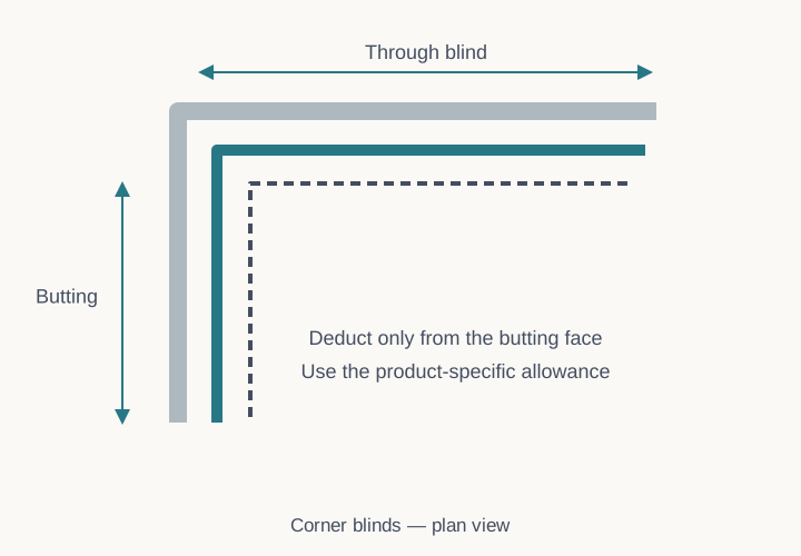
Measure each face from the corner to the outside architrave edge, adding the product's required overlap at the exposed outer end. Subtract the applicable amount below from the butting blind only. Keep the run-through width unchanged.
Butting-width deductions
Single roller: 85 mm. Double roller: 100 mm. Timber/PVC Venetian: 80 mm. Aluminium Venetian, 25 mm slats: 40 mm; 50 mm slats: 80 mm. Vertical, 89 mm slats: 103 mm; 127 mm slats: 135 mm. Roman: 50 mm. Curtain track: bracket projection plus 5 mm, using the minimum setting for an adjustable bracket. For a butting blind inside a corner pelmet, deduct a further 5 mm.
Roller example
If both measured faces are 2000 mm, the single roller running through stays 2000 mm wide. The butting roller is 2000 − 85 = 1915 mm wide. Label the faces and their roles in the room name.
Corner pelmet widths
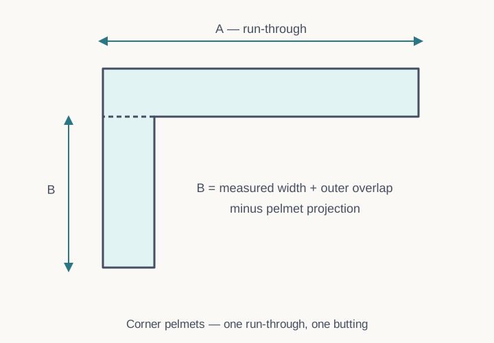
Check at least 35 mm of free space beyond each exposed outer architrave edge. Measure each face from the inner corner to its outer trim edge and add 30 mm at the exposed end where space allows. Subtract the chosen pelmet projection—80, 100, 120, 150 or 200 mm—from the butting pelmet only.
Corner pelmet example and returns
Two 1400 mm readings become 1430 mm after outer overlap. With a 100 mm projection, the run-through stays 1430 mm and the butting piece becomes 1330 mm. In the illustrated A/B arrangement, A has a right return and no left return; B has a left return and no right return. Send a plan for a mirrored or unusual arrangement. Bay pelmets need a separate checked drawing.
Half-glass and French doors
Check the door and hardware
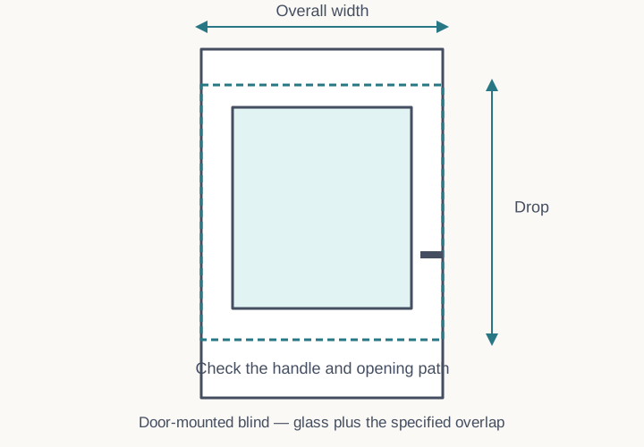
These methods cover roller, Roman and Venetian blinds on a door. Measure the glass and check the door handle, locks and opening path before selecting the overlaps. For a roller, request the smaller 32 mm clutch and tube in the order notes.
Single roller blinds
Add 50–100 mm overall to the glass width and at least 100 mm to the glass drop, normally 50 mm at the top and bottom. Under-roll fabric sits approximately 10 mm from the door; the full brackets project about 80 mm. A 50 mm total width addition leaves only about 8–10 mm fabric coverage per side after hardware. Allow for around 20 mm at the chain end and 12–15 mm at the pin end when checking coverage.
Roman blinds
Add 40–100 mm overall to the glass width and 100 mm to its drop. Check approximately 40 mm projection when lowered and 55 mm when raised. Confirm that the handle and the opening door remain clear of the stack.
Venetian blinds
For 25 mm aluminium Venetians, add 20–100 mm overall to the glass width and 100 mm to the drop; allow about 45 mm projection. For 50 mm PVC or timber Venetians, use the same width/drop additions and allow 70–80 mm projection. Adjust the planned coverage where handles or other fittings restrict it.
Bay windows: rollers, Venetians, Romans and verticals
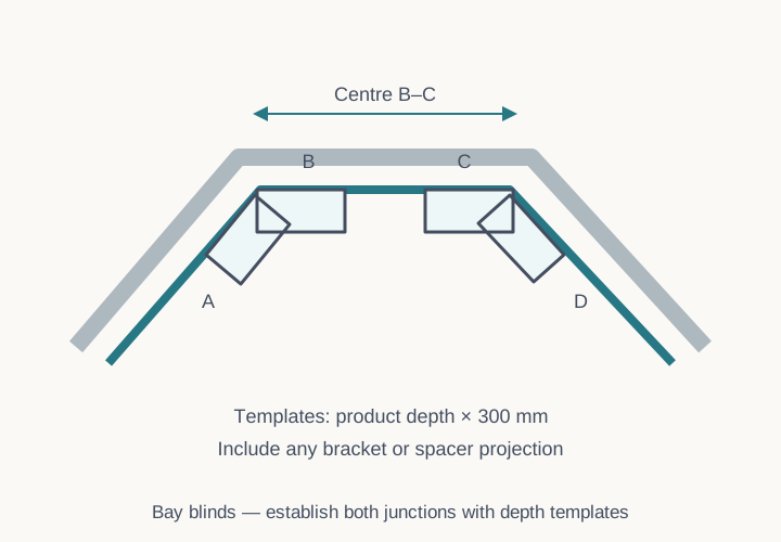
1. Make two depth templates
Cut two cardboard strips 300 mm long. Their width must equal the selected product depth, including any extra extension-bracket or spacer projection. Check that the templates fit within the recess for an inside fit. For face fit, hold them at 90° to the architrave face.
Template depths
Single roller: 70 mm. Double roller: 90 mm. Aluminium Venetian, 25 mm slats: 55 mm for this bay template; 50 mm slats: 70 mm. PVC/timber Venetian: 80 mm. Vertical, 127 mm slats: 80 mm; 89 mm slats: 65 mm. These are template depths for establishing bay junctions; check the product's separate operating-clearance requirements too. Confirm the headboard depth for Romans.
2. Mark both junctions
Bring the front corners of the two strips together at the left junction and mark A and B as shown. Repeat at the right junction to mark C and D. Keep the strips on the intended fixing plane throughout.
3. Measure the three widths
Measure the centre treatment between B and C. Measure the left treatment from A towards its outer finish and the right treatment from D towards its outer finish. Follow the strip-corner references in the drawing and keep the three labelled figures together.
4. Check and order
Label the pieces Bay Left, Bay Middle and Bay Right and select recess or face fit. Make no further deductions; the middle blind receives the required small factory allowance. Over-roll normally reduces fabric gaps for roller bays. Plantation shutters use a different measuring system, and bay pelmets or other products need a checked plan and photographs.