400+ 5 Star Reviews SureFit™ Protection Australia-wide delivery

My Direct Blinds / Installation

Panel Glide blinds installation guide

Fit the brackets and track, then attach the wand and fabric panels for the supplied face-fit manual system.

01   Identify the supplied system

These fitting steps cover the My Direct face-fit manual Panel Glide. Match the brackets and track profile to the parts supplied. Use the matching three-, four- or five-panel drawings for your supplied system.

Check the track, connecting rails, carriers, stoppers, wand eyelet, brackets and fabric panels against the supplied order. Use the matching component and bracket drawings in this guide.

02   Choose fixings for the surface

Check the delivered fixing pack before starting; bracket-fixing screws may need to be sourced separately. Use the fixing reference below for curtains and blinds, excluding shutters, and obtain any missing fixings suitable for the surface.

Use the product-specific anchoring instructions with this general reference. Select fixings to suit the actual wall construction, bracket and load.

SurfaceFixing reference
WoodRecess: 3/4 inch (20 mm), 8 gauge. Face: 1/2 inch, 8 gauge.
Steel1/2 inch, 6 gauge.
CeilingToggle bolt.
PlasterboardWall mates.
Aluminium1/2 inch, 8 gauge, or tech screw.
BrickGreen plug and 1 1/2 inch, 8 gauge self-tapper.

03   Fix the brackets

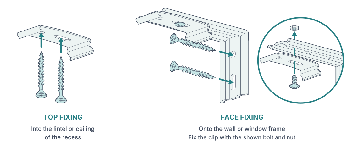
For face fit, screw the wall brackets to the wall or window frame. Attach the track clip to the wall bracket using the illustrated bolt and nut. Use fixings suitable for the mounting surface and the load.

For a supplied and confirmed top-fit configuration, pass the screws through the track clip into the lintel or ceiling of the recess, as illustrated.

Ceiling bracket and face-fit adapter assembly.
Ceiling bracket and face-fit adapter assembly. Open the illustration for a larger view.

04   Clip the track into place

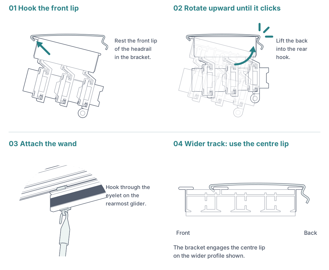
Rest the headrail’s front lip in the bracket’s front hook. Rotate the rear of the headrail upward until it snaps into the rear hook. Check each bracket is fully engaged.

For the wider track profile shown, engage the bracket’s front hook with the centre lip of the headrail, rather than its outer front lip.

Engage the front hook, snap in the rear and attach the wand.
Engage the front hook, snap in the rear and attach the wand. Open the illustration for a larger view.

05   Attach the wand and fabric

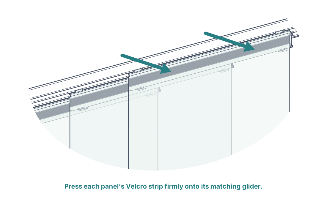
Hook the wand through the eyelet at the end of the rearmost glider. Press each fabric panel’s rear Velcro strip firmly onto the matching strip on its glider. Check all panels are attached and traverse freely.

Press each fabric panel onto its matching glider strip.
Press each fabric panel onto its matching glider strip. Open the illustration for a larger view.

06   Bracket projection reference

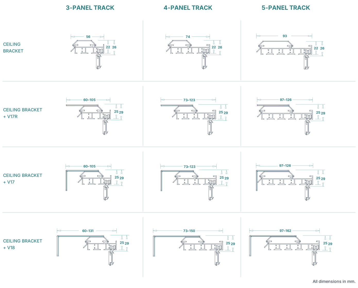
The drawing set gives track widths of 56 mm, 74 mm and 93 mm for three-, four- and five-panel tracks. Its ceiling-bracket sections show heights of 22 mm and 26 mm; sections with V17R, V17 or V18 brackets show 25 mm and 29 mm as illustrated.

For V17R or V17 combinations, the illustrated projections are 60-105 mm, 73-123 mm and 97-126 mm respectively. For V18 combinations, they are 60-131 mm, 73-150 mm and 97-162 mm. These are section-drawing dimensions, not installation screw spacing.

Bracket projections and dimensions.
Bracket projections and dimensions. Open the illustration for a larger view.

Installation help

Edition 2 · 13 September 2026

0
Cart
Empty CartYour cart is emptyReturn to Shop
Secure Checkout
Fast Shipping
Easy Returns